Advertisement
Quick Links
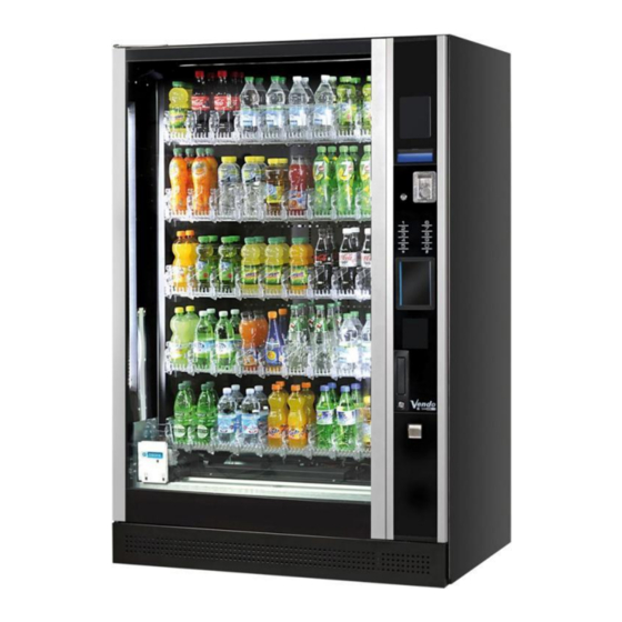
User and maintenance manual
G-Drink Design Line
G-Drink Design Line OutDoor
SandenVendo Europe S.p.A.
Regione Cavallino,2
15030 Coniolo (AL) - Italy
Tel. +39 0142.335111
Fax +39 0142.562348
E-mail:
website:
SVE DL9 - SVE DL6
SVE DV9 - SVE DV6 - SVE DC6
SVE DM9 - SVE DM6
SVE DL9OD - SVE DL6OD
SVE DV9OD - SVE DV6OD - SVE DC6OD
SVE DM9OD - SVE DM6OD
marketing@sandenvendo.it
www.sandenvendo.com
Advertisement

Related Manuals for Vendo SVE DL9


Summary of Contents for Vendo SVE DL9
- Page 1 User and maintenance manual G-Drink Design Line SVE DL9 - SVE DL6 SVE DV9 - SVE DV6 - SVE DC6 SVE DM9 - SVE DM6 G-Drink Design Line OutDoor SVE DL9OD - SVE DL6OD SVE DV9OD - SVE DV6OD - SVE DC6OD SVE DM9OD - SVE DM6OD SandenVendo Europe S.p.A.
- Page 2 SandenVendo Italian Branch of Sanden International (Europe) Limited (SVI) Regione Cavallino, 2 15030 Coniolo (AL) Italy Tel.:+ 39 0142 335111 Fax.:+ 39 0142 562348 e-mail: marketing@sandenvendo.it www.sandenvendo.com SandenVendo German Branch of Sanden International (Europe) Limited (SVG) Spangerstrasse 22 40599 Dusseldorf Germany Tel.: + 49 211 740390 Fax: + 49 211 7488541...
- Page 3 Index 1 GENERAL INFORMATION ....................4 1.1 Purpose of Manual ....................... 4 1.2 Interested people ........................4 1.3 Responsibility ........................6 1.4 Manufacturer ........................7 1.5 Service Centres ........................7 1.6 Warranty ..........................7 1.7 General safety warnings ....................... 8 1.8 Symbols ..........................
- Page 4 Index 7.8 General Cleaning Operation ....................51 7.9 Recommended Cleaning Products ..................52 7.10 Safety device for cleaning ....................52 8 INFORMATION – DANGER SIGNS ................53 9 TROUBLESHOOTING GUIDE ..................55 10 STORAGE AND CLEARANCE ..................57 10.1 Storage ..........................57 10.2 Clearance (disposal) ......................
- Page 5 Instructions for the installer, maintenance technician and final user CAUTION: FAILURE TO ABIDE BY THE INSTRUCTIONS CONTAINED THIS MANUAL MAY INVOLVE DAMAGES TO THE VENDOR AND/OR PERSONNEL Should this manual be lost or damages, you may ask for a copu from the manufacturer, enclose the serial number of your vending machine with youur request.
-
Page 6: General Information
Instructions for the installer, maintenance technician and final user 1 GENERAL INFORMATION 1.1 Purpose of Manual The manual contains the correct procedures for loading, usage, regular extra-ordinary maintenance installation vending machines. This manual is a very important part of the vendor and therefore must be kept intact and available for the whole productive life of the vendor. - Page 7 Instructions for the installer, maintenance technician and final user Technicians allowed to operate one this vending machines Operator (person who only loads the machine with products to be sold) o The operator can only load products to be sold in the vending machine. o Doing this operation the operator should never move the protective lower carter as indicated on the related safety icon-label on...
- Page 8 Instructions for the installer, maintenance technician and final user use of the appliance in a safe way and understand the hazards involved. Children shall not play with the appliance. Cleaning and user maintenance shall not be made by children without supervision. 1.3 Responsibility The responsibility of the manufacturer is limited to the correct usage of the vendor...
- Page 9 Instructions for the installer, maintenance technician and final user 1.4 Manufacturer “SandenVendo Europe S.p.A.” claims more than 50 years of experience in the manufacturing of Vending machines, and it is the technical know-how acquired, after years of researches and close contact with the production and commercialisation at global level that represents the best warranty SandenVendo Europe S.p.A.
- Page 10 Instructions for the installer, maintenance technician and final user The warranty does not include, damages to the vendor caused by: Transport and/or handling Operator errors Lack of maintenance contemplated for in this Manual Failures and/or breakages not caused by the malfunction of the vending machine 1.7 General safety warnings ...
- Page 11 Instructions for the installer, maintenance technician and final user If the power cable is damaged, it should be substituted by the manufacturer or by his after- sales technicians or however by an equally qualified person, in order to avoid any risks ...
- Page 12 Instructions for the installer, maintenance technician and final user The pictures and illustrations in this document are only indicative. SandenVendo Europe S.p.A. recalls that the technical and performance of products can change without notice. “SandenVendo Europe S.p.A.” reserves the right of making changes on their vending machines without any advice;...
- Page 13 Instructions for the installer, maintenance technician and final user 1.8 Symbols In the manual and/or on the vendor, warning areas have been indicated with signs, plates, symbols or icons showing danger or obligations in each case The symbols used in the manual and on the vendor are the following: SIMBOL MEANING COMMENT...
-
Page 14: Machine Features
Instructions for the installer, maintenance technician and final user 2 MACHINE FEATURES 2.1 Differences between models The vending machine line G-Drink Design Line is composed by many models that have the following differences: Model DM6 Model DC6 Dimensions DC6 - DM6 Height (A) 1830 mm Width (B) - Page 15 Instructions for the installer, maintenance technician and final user SVE DL9 SVE DL6 SVE DV9 SVE DV6 SVE DC6 SVE DL9OD SVE DL6OD SVE DV9OD SVE DV6OD SVE DC6OD SVE DM9 SVE DM6 SVE DM9OD SVE DM6OD © SandenVendo Europe SpA...
- Page 16 Instructions for the installer, maintenance technician and final user 2.2Technical Features G-Drink Design Line Dimensions DV6 - DM6 DV9 - DM9 DV6 - DM6 DV9 - DM9 Height (A) with feet 1900mm 1900mm Height (A) with levelling screw 1830mm 1830mm Width (B) 950mm 1220mm...
- Page 17 Instructions for the installer, maintenance technician and final user 2.3 Description of Components 1. Card reader cover 2. Display 3. Coin introduction 4. Keyboard 5. Product eyelet 6. Door lock 7. Coin return 8. Products window 9. Lower grid FIG. 2.3 1.
- Page 18 Instructions for the installer, maintenance technician and final user 2.4 Vertical Sale Mechanism The new models G-Drink Design Line DV6 - DC6 - DM6 - DV9 and DM9 are ecquiped wit the new X axis mechanism in vertical. The new x axis mechanism has the advantage that if one or more sales are failed (for example, the product falls into the machine) the vending machine does not go out of service, but continues to works, because on the basis of the vending machine was created a compartment in which the products fallen not hamper the functioning of the vending...
- Page 19 Instructions for the installer, maintenance technician and final user 2.5 OutDoor Version G-Drink Design Line OutDoor DL6OD - DV6OD Dimensions DL9OD - DV9OD - DM9OD DC6OD - DM6OD Height (A) with feet 1942 mm 1942 mm Height (A) with levelling screw 1872 mm 1872 mm Width (B)
- Page 20 Instructions for the installer, maintenance technician and final user 2.5.1 Outdoor Components 1) Heated glass 2) Protection trim door glass 3) FMP Control Panel 4) Out-Door Refrigerant Unit 5) Rear cover 6) Roof 7) Gasket 8) Gasket support 9) Display protection 10) Coin return button protection 11) Keypad protection 12) Flap h ole cover...
- Page 21 Instructions for the installer, maintenance technician and final user 2.6 Referral programming manual All the machine’s control and operation settings can be set through the programming routine of the SVE01 electronic board. The programming routine of the electronic board is described in the SVE01 PROGRAMMING MANUAL supplied with the vending machine.
-
Page 22: Installation
Instructions for the installer, maintenance technician and final user 3 INSTALLATION 3.1 Transport and Positionning FIG. 3.1 NET WEIGHT MODEL A (mm) B (mm) C (mm) (Kg) DL6 - DV6 1900 DC6 - DM6 DL9 - DV9 - DM9 1900 1235 DL6OD - DV6OD 1960... - Page 23 Instructions for the installer, maintenance technician and final user 3.2 Characteristics of Installation Area CAUTION: THE MACHINE IS NOT SUITABLE FOR OUTDOOR INSTALLATION WITHOUT THE OUTDOOR KIT CAUTION: DO NOT USE JETS OF WATER TO CLEAN VENDOR, DO NOT PLACE THE VENDOR IN AREAS WHERE JETS OF WATER ARE USED Environmental conditions for installing vendor ...
- Page 24 Instructions for the installer, maintenance technician and final user 3.3 Removing of Wooden Bases To remove wooden bases, work as follows: With a transpallet lift the machine from the floor (holding it from the Front) With an adjustable wrench unscrew the screws that fasten the wooden base to the machine: 2 screws on the right hand side and 2 screws on the left hand side ...
- Page 25 Instructions for the installer, maintenance technician and final user 3.5 Stability The stability of the SandenVendo vending machine is granted whether the vending machine empty or full and / or with the door open. The overturning of vending machine without external influences is quite impossible. Against the vandalism, such as possibility of tilting the Vending machine, the following optional kits are applicable to meet your needs.
- Page 26 Instructions for the installer, maintenance technician and final user 3.6 Connection to Power Mains SERVICE CORD INSTALLATION FIG.2 FIG.1 1) Unscrew the 2 screws in FIG.1 2) Pull out the service cord until the fastening plate appears as in FIG.2 3) Fasten the plate with the 2 screws as in FIG.3 FIG.3...
- Page 27 Instructions for the installer, maintenance technician and final user 3.7 Coin Mechanism Installation Hook the coin box on the 3 screws (E) located on the coin box door (F). Check that the coin slot on the coin box is in line with the outlet of the coin channel (G) and that the distance between the two parts is approx.
- Page 28 Instructions for the installer, maintenance technician and final user 3.8 How to split the vending machine model DC6 - DM6 - Disconnect the vending machine from the power supply and put the service cord into the drawer - Make sure the vending machine is stood on 6 levelling screw - Open the drawer and remove the fixing bracket (see image 1) - Disconnect all the harnesses that coming from the cabinet (N.B.
- Page 29 Instructions for the installer, maintenance technician and final user - Remove the first screw that fixes the base bracket blocker and loosen the other two (see image 5) - Slide upwards the base bracket blocker along the slot - Unscrew the two screws that fix the control panel box Loosen Unscrew - Push the control panel unit backwards forcefully to release it from the screws on the back...
- Page 30 Instructions for the installer, maintenance technician and final user To assemble the vending machine you need to do as follow: - Place the control panel unit to the right side of the vending machine, be careful to the harnesses (see image 10) - Pull forward until the control panel unit properly fits the screw on the back of the cabinet (see image 11) - Fix the control panel unit with screws on the top of the cabinet...
- Page 31 Instructions for the installer, maintenance technician and final user - Fix the lower front of the control panel unit to the cabinet - Reinstall the carter under the door - Place the drawer near the control panel unit and connect all the harnesses on the transformer box - Reinstall the drawer into the vending machine, making sure all the harnesses are properly connected...
-
Page 32: Access To Internal Parts
Instructions for the installer, maintenance technician and final user 4 ACCESS TO INTERNAL PARTS Access inside the machine (maintenance area) is possibile yusing the specially provided key supplied with the vendor (rif. Fig. 4.1). Access to the service area is possible only using a specially provided tool. Hereunder is a list of the service areas of the vending machine : ... -
Page 33: Using The Vending Machine
Instructions for the installer, maintenance technician and final user 5 USING THE VENDING MACHINE 5.1 Warnings CAUTION: DO NOT LOAD THE VENDOR WITH PRODUCTS DIFFERENT FROM THE ONES RECOMMENDED BY THE MANUFACTURER (refer to chapter PROPER USE ) 5.2 Proper Use The vending machine G-DRINK DESIGN LINE (DL6-DL9-DV6-DV9-DC6-DM6-DM9) have been designed and built for vending and distributing the following products: PRODUCTS SIZE:... - Page 34 Instructions for the installer, maintenance technician and final user 5.3 Loading Products The products that can be delivered are loaded in each tray inside the machine. TRAY 1 TRAY 2 TRAY 3 TRAY 4 TRAY 5 TRAY 6 TRAY 7 FIG.
- Page 35 Instructions for the installer, maintenance technician and final user Attention: It is absolutely forbidden to step on the lift during loading Attention: It is absolutely forbidden to use the tray as support 1) Withdraw the trays by lifting slightly before pulling toward you until the tray stop is reached.
- Page 36 Instructions for the installer, maintenance technician and final user 3) Place the products in the selection in front of the pusher, until completely loaded and then push the tray back to it’s working position. Important: Load only clean trays. Dirty slider surfaces may cause malfunctions. The slider surfaces and pushers of the drawers must be regularly checked and cleaned for proper functioning.
- Page 37 Instructions for the installer, maintenance technician and final user 5.3.1 Loading of bottom left side tray Follow below procedures for extracting only the first tray on the bottom left side: 1) Manually open the vend door VEND DOOR PRODUCT CATCHING BUCKET 2) The product bucket moves from left to right allowing extraction of the tray a.
- Page 38 Instructions for the installer, maintenance technician and final user 5.4 How to remove the trays To remove the trays do the following: - Place the palm of your hand under the tray and lift it slightly to allow the unhooking from the shelf.
- Page 39 Instructions for the installer, maintenance technician and final user Back panel internal cabinet Cabinet right front side Cabinet left front side R: reference hole Shelf 1 is fixed. Counting starts from bottom with hole no. 1. Every 10th position is indicated by a reference Hole (indicated with “R” in the photo). The shelf assy must be inserted into the same hole position as the shelf supports (See example: Second shelf, position 7).
-
Page 40: Main Switch
Instructions for the installer, maintenance technician and final user 5.6Start-up To start-up the Vending machine, work as follows: Assure that the plug is connected to the supply mains. Give power to the Vendor: ppress the luminous green button MAIN SWITCH situated on the transformer box inside of the machine (on the sliding panel next to the cell). - Page 41 Instructions for the installer, maintenance technician and final user 6 DESCRIPTION AND FUNCTION OF CONTROL UNIT 6.1 Control Unit EASY CAREL The electronic control unit EASY CAREL regulates and controls the refrigerant system and all its components: The compressor, the fans, the defrosting, and is independent of the control of the board SVE01, which control the electronics of the distributor.
- Page 42 Instructions for the installer, maintenance technician and final user 6.1.2 Keyboard Key 1 "UP", in normal function if pushed for more than 1 second, it visualizes the temperature of probe 2 (evaporator). If pushed during the visualization of the set point it increases the set value.
- Page 43 Instructions for the installer, maintenance technician and final user 6.1.5 Description of the main signals and alarms The error codes are displayed on the display alternating with the temperature gauge. ERROR DESCRIPTION The compressor has a timing delay when starting, therefore the LED of the compressor on the display starts to flash.
- Page 44 Instructions for the installer, maintenance technician and final user 6.2 Control Unit CAREL ir33 The electronic control unit CAREL ir33 regulates and controls the refrigerant system and all its components: the compressor, the fans, the defrosting and is independent of the control of the board SVE01, which control the electronics of the distributor.
- Page 45 Instructions for the installer, maintenance technician and final user ICON FUNCTION DESCRIPTION Normal operation Start up BLINK ON if at least one timed defrost If at least 1 ON if has been set. At start-up, timed defrost No timed defrost real-time CLOCK comes ON for a few seconds to...
- Page 46 Instructions for the installer, maintenance technician and final user 6.2.2 Keyboard Automatic address Icon Normal operation Start up assignment request pressing the button pressing together with other buttons alone If pressed for more than 5 PRG+SET: if pressed together for more than If pressed for more seconds, accesses the If pressed for more...
-
Page 47: Maintenance
Instructions for the installer, maintenance technician and final user 6.2.3 Displaying and setting the set point Press SET for more than 1 second to display the set point; ▲ ▼ Increase or decrease the set point using the buttons respectively, until reaching the desired value;... - Page 48 Instructions for the installer, maintenance technician and final user 7.2 Preventive Maintenance In order to guarantee a good performance of the Vendor the following maintenance operations are recommended: Check the vending machine and its surroundings area, check for signs of rust on the cabinet and obstructions of air vents ...
- Page 49 Instructions for the installer, maintenance technician and final user 7.3 Removing and Installing the Bucket BEFORE STARTING THE VENDING MACHINE DISCONNECT FROM THE POWER SUPPLY 1. Move the bucket to the middle with caution. 2. Remove the two screws. 3. Put your finger under the bucket and unhook the hook and lift it up.
- Page 50 Instructions for the installer, maintenance technician and final user 7.4 Led Tube Replacement To replace a LED tube, work as follow: Open the door. Turn off the machine pressing the main switch. Take out the LED-tube from the fastening clips. ...
- Page 51 Instructions for the installer, maintenance technician and final user 7.5 Flap Photocell Adjustment The identification of the product is performed as follows: The hand transports the product to the inner delivery flap and releases the product into the delivery chamber - Product detection is performed by the flap switch. If the product is detected when passing the inner flap but not from the delivery chamber sensor the delivery door is opened.
- Page 52 Instructions for the installer, maintenance technician and final user 7.6 Cleaning of the Vending Machine The general cleaning of the vendor must be done to maintain the efficiency of the vendor. The following is recommended: Check the vendor and the surrounding area, check for rust on the cabinet and obstructions in the air vents ...
- Page 53 Instructions for the installer, maintenance technician and final user 7.8 General Cleaning Operation To have perfect working conditions it is important that the machine is cleaned and kept well. Please follow the below indications Clean the Vendor with water and soap. The exterior may be waxed with any good automobile wax Cleaning of painted Small internal signs of corrosion can be removed using sand paper...
- Page 54 Instructions for the installer, maintenance technician and final user Never use: Cleaning products that are chemically aggressive. Cleaning products that are abrasive. General Never clean with blades or pointed objects. precautions Before start of cleaning turn off power supply. ...
- Page 55 Instructions for the installer, maintenance technician and final user 8 INFORMATION – DANGER SIGNS A series of warning messages are written inside all SandenVendo Europe vending machines, this is to make the user aware of the dangers that exist whilst working on the machine.
- Page 56 Instructions for the installer, maintenance technician and final user 12) Identification of the Vendor and main technical details Production details: Month/Year 13) CAUTION: Be very careful when handling delivery mechanisms 14) Final inspection certificate © SandenVendo Europe SpA...
-
Page 57: Troubleshooting Guide
Instructions for the installer, maintenance technician and final user 9 TROUBLESHOOTING GUIDE The following section provides self-diagnostics to aid you in the troubleshooting process. Here below is a list of possible causes together with the recommended solutions to eliminate the problems CAUTION: In case of failure or malfunctioning contact only qualified personnel at our service centre Please remember that our after sales assistance is completely available for... - Page 58 Instructions for the installer, maintenance technician and final user ERROR POSSIBILE CAUSE RECOMMENDED SOLUTIONS The condenser fan is not Check the circuit. Replace the motor. working. Check if the fan is blocked.. Check if the fans of the condenser are Dirty condenser.
- Page 59 Instructions for the installer, maintenance technician and final user 10 STORAGE AND CLEARANCE 10.1 Storage Should the vending machines not be used immediately or is stowed for long periods, check that it is correctly packed and positioned vertically. It should be stored in a closed, but well ventilated room and which does not have particular characteristics hazardous to the machine’s components, in particular the electronic ones.
- Page 60 Instructions for the installer, maintenance technician and final user 10.3 Person in Charge of Disposal Directive WEEE 2002/96/CE enforces the obligation NOT to dispose WEEE (Waste Electrcial and Electronic Equipment ) as household waste and to select this waste fro separate collection.
- Page 61 Revision Data Changes Page 20/05/2013 Creation Manual 31/10/2013 Update point 1 General Information Update point 3.5 Stability Change some image Change heading and footer 20/11/2013 Moved page of Feature board box Update point 5.4 loading operation Update point 7.8 General Cleaning Operation Update point 7.5 Flap Photocell Adjustment Update point 5.2 Proper Use Inner...
Need help?
Do you have a question about the SVE DL9 and is the answer not in the manual?
Questions and answers