
Related Manuals for Vendo V21


Summary of Contents for Vendo V21
- Page 1 Vendo V21 Manual Chameleon Identi ed Equipment SandenVendo America, Inc. Vendo P/N 1124557 10710 Sanden Drive • Dallas, Texas 75239 • (800) 344-7216 • FAX (800) 541-5684 Rev. B...
- Page 2 CHAMELEON TABLE OF CONTENTS Part #1169256 09/2008...
-
Page 3: Table Of Contents
REFRIGERATION HAZARDS ..............Page S-10 SUBSTITUTIONS AND MODIFICATIONS ..........Pages S-11 - S-12 CONSUMER SAFETY WARNING .............. Page S-13 PARTS, SALES, AND SERVICE CENTERS OF VENDO/SANDEN CO..Pages S-14 - S-15 GENERAL INFORMATION ................. Pages G1 - G12 GENERAL INFORMATION ................Page G-2 INITIAL SET-UP .................. - Page 4 TROUBLESHOOTING ................Pages T-1 - T-12 VENDO WARRANTY .................. Pages T-2 PARTS RETURN PROCEDURE ..............Page T-3 TROUBLESHOOTING GUIDE ..............Pages T-4 - T-11 Part #1169256 09/2008...
-
Page 5: Safety Section
CHAMELEON SAFETY SECTION Part #1169256 09/2008... -
Page 6: A Commitment To Safety
A COMMITMENT TO SAFETY SandenVendo America, Inc. is committed to safety in every aspect of our product design. SandenVendo America, Inc. is committed to alerting every user to the possible dangers involved in improper handling or maintenance of our equipment. The servicing of any electrical or mechanical device involves potential hazards, both to those servicing the equipment and to users of the equipment. -
Page 7: Vendor Installation
SECTION I: VENDOR INSTALLATION Vendors are large, bulky machines of signifi cant size and weight. Improper handling can result in injury. When moving a vendor, carefully plan the route to be taken and the people and equipment required to accomplish the task safely. Remove all tape, shipping sealant, and Styrofoam from the vendor. - Page 8 Part #1169256 09/2008...
- Page 9 SECTION I: VENDOR INSTALLATION (CONTINUED) For Type 1 and Type 2 outlets, test for Grounding and Polarization as follows: With a test device (volt meter or test light), connect one probe to the receptacle’s neutral contact and the other to the live contact. The test device should show a reaction.
- Page 10 SECTION I: VENDOR INSTALLATION (CONTINUED) Door Support (Figure 2) The door support is to ensure that the outer door closes squarely to the cabinet. Raising the door can also ensure proper alignment of the door latch. FIGURE 2 Door Latch Alignment (Figure 3) After any door adjustment, the fl...
-
Page 11: Electrical Hazards
SECTION II: ELECTRICAL HAZARDS GENERAL SandenVendo America, Inc. vending machines are provided with the appropriate power supply setting for your area. Some models are equipped with step-down transformers, as required. This enables the vending machine to operate on different main voltages. Refer to Section I. - Page 12 SECTION II: ELECTRICAL HAZARDS (CONTINUED) Servicing with “Power Off” For maximum safety, unplug the service cord from the wall outlet before opening the vendor door. This will remove power from the equipment and avoid electrical and mechanical hazards. Service personnel should remain aware of possible hazards from hot components even though electrical power is off.
-
Page 13: Mechanical Hazards
SECTION III: MECHANICAL HAZARDS Servicing of Moving Parts and Assemblies When servicing assemblies involving moving parts, use extreme caution!! Keep fi ngers, hands, loose clothing, hair, tools, or any foreign material clear of entrapment. As noted before under the electrical hazards section, Power On servicing should only be performed by qualifi... -
Page 14: Refrigeration Hazards
SECTION IV: REFRIGERATION HAZARDS GENERAL Refrigeration systems involve both electrical power and mechanical action. These systems may present any of the potential dangers shown in the sections on electrical and mechanical hazards contained in this manual. See Sections II and III for further information. -
Page 15: Substitutions And Modifications
SECTION V: SUBSTITUTIONS AND MODIFICATIONS GENERAL Unauthorized changes or the substitution of unauthorized parts can compromise the equipment designs. This can result in unsafe conditions for either the service personnel or the equipment users. Always refer to the appropriate parts and service manual for replacement parts and maintenance instructions. - Page 16 SECTION V: SUBSTITUTIONS AND MODIFICATIONS (CONTINUED) WARNING: THIS APPLIANCE MUST BE EARTHED. IMPORTANT! The wires in the main leads are colored in accordance with the following code: 110v/120v 220v/240v Green Green and Yellow ......Earth White Blue ........... Neutral Black Brown ..........
-
Page 17: Consumer Safety Warning
SECTION VI: CONSUMER SAFETY WARNING WARNING: VENDOR CAN BE OVERTURNED IF SUFFICIENT FORCE IS APPLIED AND MAY RESULT IN SERIOUS INJURY OR DEATH. GENERAL There have been incidents, including fatalities, when vending machines have been vandalized by being pulled over in an attempt to obtain free product or money. To warn of the danger involved in tipping, shaking, or rocking the vending machine, a decal has been designed to be affi... - Page 18 Sanden International Taiwan Corp. Tel: 886-2-570-6106 No, 21-6, Sec 1 Fax: 886-2-577-1959 Tun Hwa S. Rd., Taipei, Taiwan Taiwan, ROC Belgium N.V. Vendo Benelux, S.A. Tel: 32-2-268-2595 Industrial Research Park N.O.H. Fax: 32-2-268-2862 13 Font St. Landry 1120 Brussels Belgium England Vendo UK Ltd.
- Page 19 AREA ADDRESS PHONE NUMBERS Mexico Vendo de Mexico Tel: (52) 427 2718096 Carreta Mexico - Tequisquiapan Km 3.2 Fax: (52) 427 2718077 San Juan del Rio, Queretaro C.P. 76800 Mexico IMI Cornelius de Mexico, S.A. de C.V. Tel: (52 55) 5272-7904 Manual Dublan No.
- Page 20 NOTES S-16 Part #1169256 09/2008...
-
Page 21: General Information
CHAMELEON GENERAL INFORMATION Part #1169256 09/2008... - Page 22 This manual contains programming, operation, and complete parts and electrical wiring diagrams. The V21 controller is a microprocessor which will permit pricing per selection from 0.00 to 99.99. This machine also has space-to-sales programming as well as energy savings modes.
-
Page 23: Initial Set-Up
INITIAL SET-UP A. UNPACKING Remove all plastic fi lm, cardboard and tape from the outside of the vendor. Loosen any shipping devices used to secure interior parts during shipment (backspacer, shims or spacers). To remove shipping boards from base, raise vendor on a well-stabilized lifting device. Remove the leveling bolts which hold the boards in place and remove the boards. - Page 24 APPROVED FOR OUTDOOR USE BASIC MODEL UNIT SERIAL NO. CHARGE OZ. R-134a AMPS REFRIGERATED VENDING MACHINE DESIGN PRESSURE - PSIg VOLTS LOW SIDE 90 HIGH SIDE 295 239L CYCLE PHASE MFD IN U.S.A. BY SANDENVENDO AMERICA, DALLAS, TX POWER REQUIREMENTS FIGURE 1 NOTE: The Model number of the vending machine is located on the top, left hand corner of the serial plate.
-
Page 25: Label Installation
FIGURE 2 FIGURE 3 LABEL INSTALLATION COIN INSTRUCTION LABEL & PRICE LABEL APPLICATION: Apply labels to a clean and dry surface. Peel backing from label and apply with fi rm, even pressure. INSTRUCTION LABEL (Refer to Figure 2 for the following information.) Coin insert “A”... -
Page 26: Alignment Checks
BASIC LOAD SET-UP (see Figure 6 on next page): The V21 machine is capable of vending a variety of products. For specifi c information, refer to the product set-up label on the machine inner door or contact the Technical Ser- vices Department of the SandenVendo America, Inc. - Page 27 Side spacers ARE NOT required for 12 oz. can vending. Vend mechanism is self priming. No need to manually prime after initial load or reload. For questions regarding product settings, contact the Vendo Technical Services Department at 1-800-344-7216 ext.3368 (US/Canada) or 559-439-1770 ext.3368.
-
Page 28: Vend Mechanism Parts Description
VEND MECHANISM PARTS DESCRIPTION The parts listed below are part of the vend motor mechanism (refer to Figure 7 on page G-9). One mechanism is required per column, except the drop sensor assembly, which is one assembly per machine. The parts are interchangeable. Setting will differ between single, double, triple, and quadruple depth. - Page 29 FIGURE 7 Part #1169256 09/2008...
-
Page 30: Vend Cycle
VEND CYCLE Several operations take place during the vend cycle: When a selection is made, the coupler and bucket rotate, product is dispensed and the bucket is then reloaded. The sequence of these operations change slightly when the column’s depth setting is changed. - Page 31 FIGURE 9 G-11 Part #1169256 09/2008...
- Page 32 NOTES G-12 Part #1169256 09/2008...
-
Page 33: Programming Section
CHAMELEON VEC 12.4 Programming Section Part #1169256 ECN# 52202 08/2010... -
Page 34: Programming
VEC 12.4 PROGRAMMING OPERATION NOTE: Some units may contain a European font display, in which case the “°” symbol will be replaced by the “ß” symbol. Example: 72°F will be 72 ß F. The VEC 12.4 Controller uses a 4-button programming system: Programming Buttons: # 1 –... - Page 35 Diagnostics: See inner door of vendor or Troubleshooting section for errors and how to clear them. Coin Payout: Coin Payout Mode allows the operator to ‘test’ for proper operation of the changer tubes. 1. Press Button 4 to enter into “Coin Payout” mode. 2.
- Page 36 Test Mode Display: Allows you to verify that all of the characters on the display illuminate. 1. At “Test Mode” press Button 4. 2. Press Button 2 to scroll until display reads “Test Mode - Display.” Press Button 4. 3. All of the characters on the display should illuminate. 4.
- Page 37 Set Price: This Mode allows you the option to price each selection to the same vend price, or price each selection button independently. 1. When display reads “Set Price” press Button 4. 2. Press Button 2 or 3 to choose selections or “All.” 3.
- Page 38 MIS Auto Reset ON - Resets if the counter is checked and after the door is closed. OFF - Does not reset. Consumer Overpay ON - A dollar bill will be accepted even if the correct change light is on and there is insuffi...
- Page 39 Depth Learning ON - The control board will “learn” the depth setting after one row of product in the column is vended. OFF - The control board will not “learn” the depth setting. Display Scroll ON - The display will scroll from Left to Right. OFF - The display will not scroll.
- Page 40 Set Language: This Mode allows you to program different languages on the controller. The current languages available are English, Spanish, and French. 1. Press Button 4 at “Set Language” mode. The current language will be displayed. 2. To change current language, press Button 4 to start language fl ashing. 3.
- Page 41 Refrigeration: If ‘Timing Features’ in Confi guration Mode are ‘Off’, you will only have access to the following features: Set Point Temperature Sensor Reading Degree Setting Fan Energy Mode Periodic Defrost Mode To change the set point temperature: 1. Press Button 4 when the display reads “Refrigeration.” 2.
- Page 42 6. Press Button 4 to save setting. 7. Press Button 1 to exit and return the display to “Refrigeration.” If the “Timing Features” in the Confi guration mode are turned ON, you will have additional access to the following modes: Enable Start Time 1 or Start Time 2 Start Day 1 or Start Day 2...
- Page 43 Return: Exits the programming mode and returns the vendor to stand-by. P-11 Part #1169256 08/2010...
-
Page 44: Wiring Diagrams
Wiring Diagram P-12 Part #1169256 08/2010... - Page 45 P-13 Part #1169256 08/2010...
- Page 46 CHAMELEON CABINET PARTS Part #1169256 09/2008...
-
Page 47: Reading A Parts List
READING A PARTS LIST ITEM NUMBER is found in two locations: It is on the drawing plate, and identifi es the part and its location; The same number is in the parts lists and ties the two together. PART NUMBER is the part number that has been assigned to a specifi c part by SandenVendo America, Inc., for easier identifi... - Page 48 Purposely left blank Part #1169256 09/2008...
-
Page 49: Hardware List
HARDWARE LIST Part #1169256 09/2008... - Page 50 Part #1169256 09/2008...
- Page 51 Part #1169256 09/2008...
-
Page 52: Cabinet Assembly
CABINET ASSEMBLY ITEM NO DESCRIPTION QTY REQ PART NO. CABINET ASSEMBLY - FOAMED HINGE PIN 389071 RAMP 1120387 LEVELING LEG 1059902 CONDENSATE PAN 1122475 DRAIN TUBE 1088449-1 FIBERGLASS EVAPORATOR BOARD 1122728 DRAIN TUBE GASKET 387837 DRAIN TUBE FUNNEL 1068678 NUT - DRAIN TUBE 387925 BRACKET - REFRIGERATION 1123527... - Page 53 Part #1169256 09/2008...
-
Page 54: Stack Assembly
STACK ASSEMBLY ITEM MODEL NUMBER DESCRIPTION PART NO. PART NO. STACK CHASSIS ASSEMBLY 1123591-02 1123591-03 MOTOR COVER 1123003 1123003 BACK SPACER ASSEMBLY 1123047-1 1123047 MOTOR HARNESS 1122918 1122918 MOTOR HARNESS W/ PRE-COOL 1124065 1124065 LOWER RETAINER 1124868 1124868 TOP STACK STRAP 1122809 1122809 FRICTION WIRE... - Page 55 C-10 Part #1169256 09/2008...
-
Page 56: Mech Plate Assembly
MECH PLATE ASSEMBLY ITEM MODEL NUMBER 721/821 DESCRIPTION PART NO. VEND MOTOR ASSEMBLY 1122820 FRONT SPACER 1122814 VEND BUCKET 1122815 CAN CLIP 1122856 * PRODUCT SPACER, 2.4 DIA 1122928 GATE 1122818 E-CLIP - GATE V801080 SPRING 390326 GATE LINK 1122819 COUPLING CAM 1122817 REAR BUSHING... - Page 57 C-12 Part #1169256 09/2008...
-
Page 58: Refrigeration Assembly
REFRIGERATION ASSEMBLY ITEM DESCRIPTION PART NO. REFRIGERATION ASSEMBLY D90 TE S 1/3 R134a CAP START 1123589 ORIFICE PLATE, SINGLE FAN 390228 TEMPERATURE SENSOR ASSEMBLY 1124254 TEMPERATURE SENSOR 1122924 TEMPERATURE SENSOR BRACKET 1124156 CLAMP, 1/4” 324099-2 PUSH MOUNT CLAMP 384692 EVAPORATOR FAN BLADE 1113562 FAN MOTOR - EVAPORATOR 42321-17... - Page 59 C-14 Part #1169256 09/2008...
-
Page 60: Power Box Assembly
POWER BOX ASSEMBLY ITEM DESCRIPTION PART NO. POWER BOX HOUSING 1148515 RELAY 1128801 CLAMP 324099-3 CORDSET 1124281 TRANSFORMER 1111201 FUSEHOLDER 387966-50 0.8 AMP FUSE (NOT SHOWN) 1053864 POWER HARNESS 1123444 FUSE LABEL 1126640 FOR A COMPLETE LIST OF HARNESSES, PLEASE SEE PAGE C-16 C-15 Part #1169256 09/2008... -
Page 61: Harness Quick Reference Guide
SandenVendo America, Inc. HARNESS QUICK REFERENCE GUIDE TRADE VENDORS PART NO. DESCRIPTION PURPOSE 721 821 621 1122905 Door Harness Connects motors, temp. sensors, transformer, drop sensors, and relays to the contol board 1111287 Selection Harness - 10 select Connects the selection buttons to the control board 1117872 Selection Harness - 8 select Connects the selection buttons to the control board... - Page 62 NOTES C-17 Part #1169256 09/2008...
- Page 63 CHAMELEON Door Parts TD-1 Part #1169256 09/2008...
- Page 64 CHAMELEON TRADE DOOR TD-2 Part #1169256 09/2008...
-
Page 65: Lock Assembly
CHAMELEON TRADE DOOR ITEM MODEL NUMBER HARDWARE DESCRIPTION PART NO. PART NO. DOOR WELD 1123712 1123713 SIGN FACE SIGN CAP 1114341 1114341-1 SIGN TRIM, VTL, RIGHT, 72” 1143505 1143505-1 SIGN TRIM, VTL, LEFT, 72” 1143516 1143516-1 BEZEL, CONSUMER INTEFACE 1143346 1143346 TRIM EYELET, CURVE 388271... - Page 66 TD-4 Part #1169256 09/2008...
- Page 67 CHAMELEON TRADE DOOR (CONTINUED) ITEM MODEL NUMBER HARDWARE DESCRIPTION PART NO. PART NO. HINGE - INNER DOOR, MALE 1121287 1121287 MOUNTING BRACKET - CONTROLLER 1077716 1077716 STAND OFF 1121740 1121740 PCBA VEC 12.1 CONTROLLER 1167867 1167867 PCBA COVER PANEL 1123049 1123049 PLATE, DBV PLUG, UPPER 1143498...
- Page 68 CHAMELEON TRADE LOCK ASSEMBLY ITEM DESCRIPTION PART NO. BRKT, SECURITY, LOCK 1143402 T-HANDLE 1002392 PIN - STUD 387601 LOCK STUD - QUICKER LOCK 1049724 SPRING 389691 E-RING RETAINER 388589 HEX WASHER 387600 SPRING - HEAVY 389691 FLAT WASHER 387718 T-HANDLE - FLANGE 1002384 VAPOR SEAL 388132...
- Page 69 TD-7 Part #1169256 09/2008...
-
Page 70: Inner Door Assembly
1121711 1121711 INNER DOOR LATCH BRACKET 1121712 1121712 FOR A COMPLETE LIST OF HARNESSES, PLEASE SEE PAGE C-16 V21 TRADE INNER DOOR LABELS - NOT SHOWN DESCRIPTION PART NO. ERROR CODE LABEL, VEC 12.1 1123715 PROGRAMMING LABEL, VEC 12.1 1123343 WIRING DIAGRAM LABEL, VEC 12.1/12.2... - Page 71 NOTES TD-9 Part #1169256 09/2008...
-
Page 72: Maintenance
CHAMELEON MAINTENANCE Part #1169256 09/2008... -
Page 73: Preventative Maintenance Suggestions
MAINTENANCE The following section is a basic guide for general maintenance and servicing of the vendor. This section is divided into three parts: (I) Preventative Maintenance, (II) Lubrication Guide, and (III) Care and Cleaning. PREVENTATIVE MAINTENANCE SUGGESTIONS: Whenever a vendor is visited on its site, the following service should be performed. Preventative maintenance will help prevent future problems with the vendor. -
Page 74: Care And Cleaning
III. CARE AND CLEANING DO NOT USE WATER JET FOR CLEANING. AVOID USING WATER OR ANY OTHER LIQUIDS NEAR ELECTRONIC COMPONENTS GENERAL PROCEDURE (painted metal areas) Wash the vendor with soap and water. The exterior may be waxed with any good automobile wax. -
Page 75: Refrigeration Operation
REFRIGERATION OPERATION The refrigeration operation section is divided into three areas: Basic Refrigeration Principle, Detailed Vending Machine Refrigeration Cycle, and Parts Description. BASIC REFRIGERATION PRINCIPLE What a refrigeration system really accomplishes is the transfer of heat. A refrigeration system removes the excess heat from a refrigerated area and then transfers it to a condenser where it is dissipated. - Page 76 DETAILED REFRIGERATION CYCLE The following is a detailed refrigeration cycle as it applies to the refrigeration system installed in SandenVendo America, Inc. equipment. (Refer to the fl ow chart in Figure 1.) As the air temperature in the cabinet rises, the electronic temperature sensor reports the air temperature to the electronic controller.
- Page 77 Part #1169256 09/2008...
-
Page 78: Refrigeration Parts Description
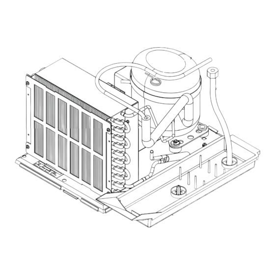
REFRIGERATION PARTS DESCRIPTION The compressor, condenser, drier, capillary tube, evaporator, and accumulator are part of a sealed system (refer to Figure 2). These items are not available separately. COMPRESSOR The compressor takes in low pressure vapor and compresses it, increasing both the pressure and the temperature. - Page 79 FIGURE 2 Part #1169256 09/2008...
- Page 80 The parts listed below are not part of the sealed refrigeration system and are available separately. START CAPACITOR - P/N: 1112805 The start capacitor is used to increase power during the start. This additional power will help get the compressor running in case there is any back pressure. STARTING RELAY –...
- Page 81 NOTES M-10 Part #1169256 09/2008...
- Page 82 CHAMELEON TROUBLESHOOTING Part #1169256 09/2008...
- Page 83 V21 VENDING MACHINES Distributor - United States / Canada / Mexico I. This warranty benefi ts each current owner of a V21 vending machine, whether that owner is the original purchaser or a transferee. II. The SandenVendo America, Inc. Company warrants each part of each new vending machine for a period of fi fteen (15) months from the date of shipment, to be free from defects in material and workmanship.
- Page 84 PARTS RETURN PROCEDURES All parts returned must be accompanied by a material return tags (P/N 1122825) Tag must clearly state the reason for the return and the Return Goods Authorization Number received from your SandenVendo America, Inc. Customer Service Rep at 1-800-344-7216. (Return tags are available from our parts department upon request).
- Page 85 Trouble Shooting Guide The V21 vendor provides self-diagnostics to aid you in the trouble shooting process. Error codes are stored in the controller’s memory when a system error is sensed. These codes can be accessed by following the procedure listed below.
- Page 86 Error DESCRIPTION OF ERROR CHECKING METHOD Corrective Action CODE Usnn Selection switch skipped - switch Switch is assigned. nn unassigned and a higher number switch is assigned. Coin Changer Changer communication error - no 1) Check that red light is fl ashing on If light is not fl...
- Page 87 Error DESCRIPTION OF ERROR CHECKING METHOD Corrective Action CODE Dollar Bill Validator Bill validator communications - No If changer or card reader is being If there are no “CC” or “rC” errors: bill validator communication for 5 used, check for “CC” or “rC” errors. 1) Check bill validator harness;...
- Page 88 Error DESCRIPTION OF ERROR CHECKING METHOD Corrective Action CODE Scaling Factor error - one Check the connections of changer Make corrections to harness or of the credit peripherals has harness; make sure changer is replace the changer if necessary. introduced a scaling factor that plugged in and working.
- Page 89 NOTE: If both sensors are not Replace sensors and test. present or are defective, the V21 will allow up to four products from each column to be vended before the column is determined to be sold out.
- Page 90 ERROR PROBABLE CAUSE CORRECTIVE ACTION No digital display; Defective display or display Check display and display harness. Replace if necessary. vendor lights on. harness. Check for a fl ashing red light If no light, replace control board. on control board. Vendor scrolls Changer out of tune.
- Page 91 ERROR PROBABLE CAUSE CORRECTIVE ACTION Compressor will not Defective overload relay Replace the overload relay. start, condenser Compressor motor rocked Replace the refer unit. fan motor running Defective capacitor Replace the capacitor. - unit hot (power to Defective PTC relay Replace the PTC relay.
- Page 92 ERROR PROBABLE CAUSE CORRECTIVE ACTION Unit will not Defective door switch. Upon opening the door, the lights and compressor should shut off. If they don’t run even in the replace the door switch. heater test mode. Defective control board Replace the board. **NOTE: Leave the compressor test mode on...
- Page 93 NOTES T-12 Part #1169256 09/2008...
Need help?
Do you have a question about the V21 and is the answer not in the manual?
Questions and answers