
Subscribe to Our Youtube Channel
Related Manuals for Kolin Primus Gold KSG-IWF-10WFY-8K1M32


Summary of Contents for Kolin Primus Gold KSG-IWF-10WFY-8K1M32
- Page 1 Original Instructions Split Air Conditioner MODELS: KSG-IWF-10WFY-8K1M32 KSG-IWF-15WFY-8K1M32 KSG-IWF-20WFY-8K1M32 KSG-IWF-25WFY-8K1M32 KSG-IWF-30WFY-8K1M32...
- Page 2 MODELS: KSG-IWF-10WFY-8K1M32 KSG-IWF-15WFY-8K1M32 KSG-IWF-20WFY-8K1M32 KSG-IWF-25WFY-8K1M32 KSG-IWF-30WFY-8K1M32...
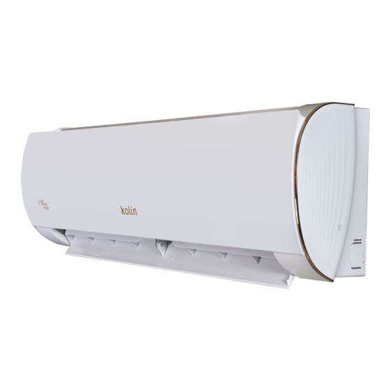
- Page 3 Thank you for choosing our product. Please read this Owner’s Manual carefully you have lost the Owner's Manual, please visit before operation and retain it for future reference.If www.kolinphil.com.ph for an electronic version. NOTE: Actual product may be different from graphics, please refer to actual products.
- Page 4 Explanation of Symbols WARNING This symbol indicates the possibility of death or serious injury. This symbol indicates the possibility of injury or damage to CAUTION property. Indicates important but not hazard-related information, used NOTICE to indicate risk of property damage. Exception Clauses Manufacturer will bear no responsibilities when personal injury or property loss is caused by the following reasons.
- Page 5 The refrigerant This appliance is not intended for use by persons Before installing the Appliance filled (including children) with reduced physical, sensory appliance, read with flammable t i l i the installation gas R32. knowledge, unless they have been given superv- manual first.
- Page 6 Safety operation of flammable refrigerant Installation notes Check whether there is fire source or potential fire source in the maintenance area. The air conditioner must be installed in a room - The naked flame is prohibited in the mainte- that is larger than the minimum room area. The nance area;...
- Page 7 Safety precautions WARNING Installation Installation or maintenance The grounding resistance must be performed by qua- should comply with nation- lified professionals. al electric safety regula- The appliance shall be in- tions. stalled in accordance with Air Conditioner should be national wiring regulations. properly grounded.
- Page 8 Safety precautions CAUTION Installation Instructions for installation For the air conditioner with- and use of this product are out plug, a circuit breaker provided by the manufac- must be installed in the turer. line. Select a location which is The yellow-green wire in out of reach for children air conditioner is ground- and far away from animals...
- Page 9 Safety precautions WARNING Operation tioner to multi-purpose soc- and Maintenance ket. Otherwise, it may cau- This appliance can be used se fire hazard. by children aged from 8 Do disconnect power supp- years and above and per- ly when cleaning air condi- sons with reduced physi- tioner.
- Page 10 Safety precautions CAUTION Operation and Maintenance frequently. Do not spill water on the re- Air conditioner gives off mote controller, otherwise burning smell. it might get broken. Indoor unit is leaking. Do not use fire or hair dry- er to dry the filter to avoid deformation or fire hazard.
- Page 11 Clean and maintenance WARNING ■ The filter should be cleaned every 2 weeks . If there is much dust in the operation environme- WARNING nt, clean frequency can be increased. ■ Turn off the air conditioner and disconnect the ■ After removing the filter, do not touch the power before cleaning the air conditioner to av- fins to avoid injury.
- Page 12 “Check the Following Items First Before Maintenance” Phenomenon Solution Check items Whether there’s od- General phenomenon analysis Eliminate the odour Odours are our source, such as source. Clean the Please check below ite ms before asking for furniture and cigare- emitted filter.
- Page 13 Installation notice WARNING sure that the unit is running in cooling mode. Then, fully close the valve at high pressure side (liquid valve). About 30-40 seconds later, fully close the valve at low pressure side (gas valve), immediately stop the unit and disconnect power.
- Page 14 Selection of installation location Requirements for electric connection Basic requirement Make sure the power supply matches with the requirement of air conditioner. Unstable power Installing the unit in the following places may cau- supply or incorrect wiring or malfunction. Pl- se malfunction.
- Page 15 Installation of indoor unit NOTE Indoor outdoor ● Pay attention to dust prevention Step 1: sures when opening the hole. Choose installation location Φ55 Φ70 5-10 Recommend the installation location to the client and then confirm it with the client. Step 2: Step 4: Install wall-mounting frame...
- Page 16 Tightening torque (N . m) drain hose Hex nut diameter 1/4'' 15~20 3/8'' 30~40 1/2'' 45~55 insulating pipe 5/8'' 60~65 NOTE ● Add insulating pipe in the indoor drain hose in order 3/4'' 70~75 to prevent condensation. ● The plastic expansion particles are not provided. Wrap the indoor pipe and joint of connection pipe with insulating pipe, and then wrap it Step 7:...
- Page 17 drain hose connection pipe Remove the wire clip; connect the power conn- band ection wire to the wiring terminal according to the color; tighten the screw and then fix the po- wer connection wire with wire clip. indoor power cord N(1) Bind them evenly.
- Page 18 Installation of outdoor unit Step 1: Fix the support of outdoor unit (select it according to the actual inst- drain vent allation situation) chassis Select installation location according to outdoor drain joint Drain hose the house structure. Fix the support of outdoor unit on the sele- cted location with expansion screws.
- Page 19 Step 6: Tighten the union nu t with torque wrench Neaten the pipes by referring to the sheet below. The pipes should be placed along the wall, bent Tightening torque(N m) Hex nut diameter reasonably and hidden possibly. Min. semidiam- 1/4'' 15~20 eter of bending the pipe is 10cm.
- Page 20 Test and operation Check after installation ● Check according to the following requirement Use vacuum pump after finishing installation. Remove the valve caps on the liquid valve and Items to be checked Possible malfunction gas valve and the nut of refrigerant charging vent. Connect the charging hose of piezometer to the Has the unit been The unit may drop, shake or...
- Page 21 Parts name Outdoor Unit Indoor Unit air inlet air inlet panel filter aux. button air outlet air outlet horizontal louver ■ If remote controller is lost or damaged, please use aux. button to turn on or turn off the air conditioner.
- Page 22 Operation and introduction of remote controller Introduction for icons on display Buttons on remote controller screen I feel Set fan speed Turbo mode Send signal Auto mode Cool mode Dry mode Fan mode Heat mode Sleep mode 8℃ heating function Power limiting operation Health mode ON/OFF...
- Page 23 ● When selecting heating mode, the air condition- Introduction for buttons on er operates under heat mode. Press "▲" or "▼" remote controller button to adjust set temperature. Press "FAN" NOTE button to adjust fan speed. Press " " / " "...
- Page 24 button TURBO no display (horizontal louvers stops Under COOL or HEAT mode, press this button to at current position) turn to quick COOL or quick HEAT mode. " " ● When selecting " ", air conditioner is blowing icon is displayed on remote controller. Press this fan automatically.
- Page 25 "T-OFF" word "OFF" will stop blinking. " " icon button SLEEP resumes displaying. Cancel T-OFF:Under the condition that T-OFF is started up, press Under COOL or HEAT mode, press this button to "T-OFF" button to cancel it. start up sleep function. "...
- Page 26 NOTE TEMP button ● Under energy-saving function, fan speed is defaulted By pressing this button, you can see indoor set at auto speed and it can't be adjusted. ● temperature, indoor ambient temperature or Under energy-saving function, set temperature can't outdoor ambient temperature on indoor unit's be adjusted.
- Page 27 Auto clean function NOTICE ● During operation, point the remote control signal Under unit off status, hold "MODE" and "FAN" sender at the receiving window on indoor unit. buttons simultaneously for 5s to turn on or turn off ● The distance between signal sender and receiving the auto clean function.
- Page 28 Configuration of connection pipe Additional refrigerant charging amount for R32 Standard length of connection pipe: 5m, 7.5m, Min. length of connection pipe. For the unit with standard connection pipe of 5m, there is no limitation for the min length of con- nection pipe.
- Page 29 smooth surface B: Remove the burrs ● Remove the burrs with shaper and prevent the burrs from getting into the pipe. improper expanding pipe shaper leaning damaged crack uneven surface thickness downwards the length is equal Working temperature range Indoor side Outdoor side C: Put on suitable insulating pipe DB/WB(°C)
- Page 30 Safety operation of flammable refrigerant 1. Transport of equipment containing flammable refrigerants See transport regulations 2. Marking of equipment using signs See local regulations 3. Disposal of equipment using flammable refrigerants See national regulations 4. Storage of equipment applications The storage of equipment should be in accordance with the manufacturer’s instructions.
- Page 31 SAFETY OPERATION OF FLAMMABLE REFRIGERANT should be kept sufficiently far away from the site of installation, repairing, removing and disposal, during which flammable refrigerant can possibly be released to the surrounding space. Prior to work taking place, the area around the equipment is to be surveyed to make sure that there are no flammable hazards or ignition risks.
- Page 32 SAFETY OPERATION OF FLAMMABLE REFRIGERANT covers, etc. If it is absolutely necessary to have an electrical supply to equipment during servicing, then a permanently operating form of leak detection shall be located at the most critical point to warn of a potentially hazardous situation. •...
- Page 33 SAFETY OPERATION OF FLAMMABLE REFRIGERANT refrigerant shall be recovered from the system, or isolated (by means of shut off values) in a part of the system remote from the leak. Oxygen free nitrogen (OFN) shall then be purged through the system both before and during the brazing process.
- Page 34 SAFETY OPERATION OF FLAMMABLE REFRIGERANT • Become familiar with the equipment and its operation. • Isolate system electrically. • Before attempting the procedure ensure that: Mechanical handling equipment is available, if required, for handling refrigerant cylinders; All personal protective equipment is available and being used correctly; The recovery process is supervised at all times by a competent person;...
- Page 35 SAFETY OPERATION OF FLAMMABLE REFRIGERANT The recovered refrigerant shall be returned to the refrigerant supplier in the correct recovery cylinder, and the relevant Waste Transfer Note arranged. Do not mix refrigerants in recovery units and especially not in cylinders. If compressors or compressor oils are to be removed, ensure that they have been evacuated to an acceptable level to make certain that flammable refrigerant does not remain within the lubricant.
- Page 36 Facebook :Kolin Philippines Instagram :kolinphilippines Youtube :kolinphilippines OFFICE PLANT Kolin Building, 1854 Sta. Rita St., Block 3, Lot 5, Main Drive Guadalupe Nuevo, Makati City First Cavite Industrial Estate Service Hotline (02) 8852-6868 Langkaan 1, Dasmariñas City, Cavite Tel. No. (046) 402-0793...
Need help?
Do you have a question about the Primus Gold KSG-IWF-10WFY-8K1M32 and is the answer not in the manual?
Questions and answers