Table of Contents
Advertisement
Quick Links
The TPS22810EVM evaluation module (EVM) allows the user to connect power to and control the 6-pin
TPS22810 load switch device. Parameters such as the on-resistance, rise time, and quick output
discharge can easily and accurately be evaluated.
switch performance specifications.
Table 1. TPS22810 Rise Time, Output Current Rating, Enable, Undervoltage Lockout, and Output
EVM
Device
TPS22810EVM
TPS22810DBV (CH1)
TPS22810EVM
TPS22810DRV (CH2)
NOTE: The TPS22810-Q1 can also be evaluated on this EVM by replacing the TPS22810DBV (U1)
with the TPS22810TDBVRQ1.
Trademarks
All trademarks are the property of their respective owners.
1
Introduction
1.1
Description
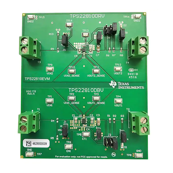
The TPS22810EVM is a two-layer PCB containing the TPS22810 load switch device. The TPS22810EVM
supports two packages for TPS22810 device, SOT-23 package (DBV) on CH1 and SON package (DRV)
on CH2. The VIN and VOUT connections to the device and the PCB layout routing are capable of
handling high continuous currents and provide a low-resistance pathway into and out of the device under
test. Test point connections allow the EVM user to control the device with user-defined test conditions and
make accurate RON measurements.
1.2
Features
This EVM has the following features:
•
V
input voltage range: 2.7 to 18 V
IN
•
Access to the VIN, VOUT, CT, QOD, GND, and EN pins of the TPS22810 load switch device
•
Onboard CIN, COUT, and CT capacitors
•
2-A maximum continuous current operation for TPS22810DBV
•
3-A maximum continuous current operation for TPS22810DRV
•
Ability to adjust the QOD resistance using jumpers
•
Ability to change COUT capacitor using jumpers
SLVUAY7B – November 2016 – Revised January 2018
Submit Documentation Feedback
TPS22810 Load Switch Evaluation Module
Discharge Characteristics
Rise Time Typical
V
IN
(μs)
Adjustable
2.7 to 18
Adjustable
2.7 to 18
Copyright © 2016–2018, Texas Instruments Incorporated
SLVUAY7B – November 2016 – Revised January 2018
Table 1
lists a short description of the TPS22810 load
Maximum Continuous
(V)
Current (A)
2
3
TPS22810 Load Switch Evaluation Module
User's Guide
Enable
Quick Output
(EN/UVLO)
Discharge
Active High
Adjustable
Active High
Adjustable
1
Advertisement
Table of Contents

Subscribe to Our Youtube Channel
Related Manuals for Texas Instruments TPS22810EVM


Summary of Contents for Texas Instruments TPS22810EVM
- Page 1 SLVUAY7B – November 2016 – Revised January 2018 TPS22810 Load Switch Evaluation Module The TPS22810EVM evaluation module (EVM) allows the user to connect power to and control the 6-pin TPS22810 load switch device. Parameters such as the on-resistance, rise time, and quick output discharge can easily and accurately be evaluated.
- Page 2 GND2 Copyright © 2017, Texas Instruments Incorporated Figure 1. TPS22810EVM Schematic General Configurations Physical Access Table 2 lists the TPS22810EVM input and output connector functionality, Table 3 describes the test point availability, and Table 4 describes the jumper functionality. Table 2. Input and Output Connector Functionality...
-
Page 3: Test Equipment
One DMM minimum needed and may require more if simultaneous measurements are required. 3.2.3 Oscilloscope A DPO2024, or equivalent. Three 10× voltage probes and one DC current probe. SLVUAY7B – November 2016 – Revised January 2018 TPS22810 Load Switch Evaluation Module Submit Documentation Feedback Copyright © 2016–2018, Texas Instruments Incorporated... -
Page 4: Test Configurations
Connect the VIN power supply to the T1/T3 terminal (VIN1/VIN2). The input voltage range of the TPS22810EVM is 2.7 to 18 V. External output loads can be applied to the load switch by using the T2/T4 terminal (VOUT1/VOUT2). The TPS22810 is active high device, and EN/UVLO pin must not be left floating. - Page 5 5. Change the default 22-nF CT capacitor C4 (C8) to vary the output voltage rise time. Figure 3 shows an example of a rise time measurement taken on the TPS22810EVM. = 12 Ω) Figure 3. TPS22810 VOUT Rise Profile (VIN = 12 V, CT = 22 nF, COUT = 10 µF, R 3.3.3...
- Page 6 Figure 5. TPS22810 VOUT Fall Profile With External Discharge Resistor of 511 Ω (VIN = 12V, CT = 22 nF, COUT = 10 µF, RL = 1000 Ω) TPS22810 Load Switch Evaluation Module SLVUAY7B – November 2016 – Revised January 2018 Submit Documentation Feedback Copyright © 2016–2018, Texas Instruments Incorporated...
- Page 7 Figure 6. TPS22810 VOUT Fall Profile With QOD = VOUT (VIN = 12 V, CT = 22 nF, COUT = 10 µF, RL = 1000 Ω) SLVUAY7B – November 2016 – Revised January 2018 TPS22810 Load Switch Evaluation Module Submit Documentation Feedback Copyright © 2016–2018, Texas Instruments Incorporated...
-
Page 8: Pcb Drawings
Figure 9 show PCB layout images. Figure 7. Top Side Placement Figure 8. Top Layer Figure 9. Bottom Layer TPS22810 Load Switch Evaluation Module SLVUAY7B – November 2016 – Revised January 2018 Submit Documentation Feedback Copyright © 2016–2018, Texas Instruments Incorporated... - Page 9 Bill Of Materials (BOM) www.ti.com Bill Of Materials (BOM) Table 6 lists the EVM BOM. Table 6. TPS22810EVM Bill of Materials Designator Value Description Package Reference Part Number Manufacturer !PCB1 Printed Circuit Board HVL178 C1, C5 CAP, CERM, 1 µF, 25 V, +/- 10%, X7R, 0805...
-
Page 10: Revision History
Deleted EVM rating sentence stating 2-A maximum continuous current in the Test Configurations section..............• Deleted 2 A from the U1 and U2 Description column in the BOM. Revision History SLVUAY7B – November 2016 – Revised January 2018 Submit Documentation Feedback Copyright © 2016–2018, Texas Instruments Incorporated... - Page 11 STANDARD TERMS FOR EVALUATION MODULES Delivery: TI delivers TI evaluation boards, kits, or modules, including any accompanying demonstration software, components, and/or documentation which may be provided together or separately (collectively, an “EVM” or “EVMs”) to the User (“User”) in accordance with the terms set forth herein.
- Page 12 FCC Interference Statement for Class B EVM devices NOTE: This equipment has been tested and found to comply with the limits for a Class B digital device, pursuant to part 15 of the FCC Rules. These limits are designed to provide reasonable protection against harmful interference in a residential installation.
- Page 13 【無線電波を送信する製品の開発キットをお使いになる際の注意事項】 開発キットの中には技術基準適合証明を受けて いないものがあります。 技術適合証明を受けていないもののご使用に際しては、電波法遵守のため、以下のいずれかの 措置を取っていただく必要がありますのでご注意ください。 1. 電波法施行規則第6条第1項第1号に基づく平成18年3月28日総務省告示第173号で定められた電波暗室等の試験設備でご使用 いただく。 2. 実験局の免許を取得後ご使用いただく。 3. 技術基準適合証明を取得後ご使用いただく。 なお、本製品は、上記の「ご使用にあたっての注意」を譲渡先、移転先に通知しない限り、譲渡、移転できないものとします。 上記を遵守頂けない場合は、電波法の罰則が適用される可能性があることをご留意ください。 日本テキサス・イ ンスツルメンツ株式会社 東京都新宿区西新宿6丁目24番1号 西新宿三井ビル 3.3.3 Notice for EVMs for Power Line Communication: Please see http://www.tij.co.jp/lsds/ti_ja/general/eStore/notice_02.page 電力線搬送波通信についての開発キットをお使いになる際の注意事項については、次のところをご覧ください。http:/ /www.tij.co.jp/lsds/ti_ja/general/eStore/notice_02.page 3.4 European Union 3.4.1 For EVMs subject to EU Directive 2014/30/EU (Electromagnetic Compatibility Directive): This is a class A product intended for use in environments other than domestic environments that are connected to a low-voltage power-supply network that supplies buildings used for domestic purposes.
- Page 14 Notwithstanding the foregoing, any judgment may be enforced in any United States or foreign court, and TI may seek injunctive relief in any United States or foreign court. Mailing Address: Texas Instruments, Post Office Box 655303, Dallas, Texas 75265 Copyright © 2018, Texas Instruments Incorporated...
- Page 15 IMPORTANT NOTICE FOR TI DESIGN INFORMATION AND RESOURCES Texas Instruments Incorporated (‘TI”) technical, application or other design advice, services or information, including, but not limited to, reference designs and materials relating to evaluation modules, (collectively, “TI Resources”) are intended to assist designers who are developing applications that incorporate TI products;...
- Page 16 Mouser Electronics Authorized Distributor Click to View Pricing, Inventory, Delivery & Lifecycle Information: Texas Instruments TPS22810EVM...
Need help?
Do you have a question about the TPS22810EVM and is the answer not in the manual?
Questions and answers