
Related Manuals for EasyStand Zing


Summary of Contents for EasyStand Zing
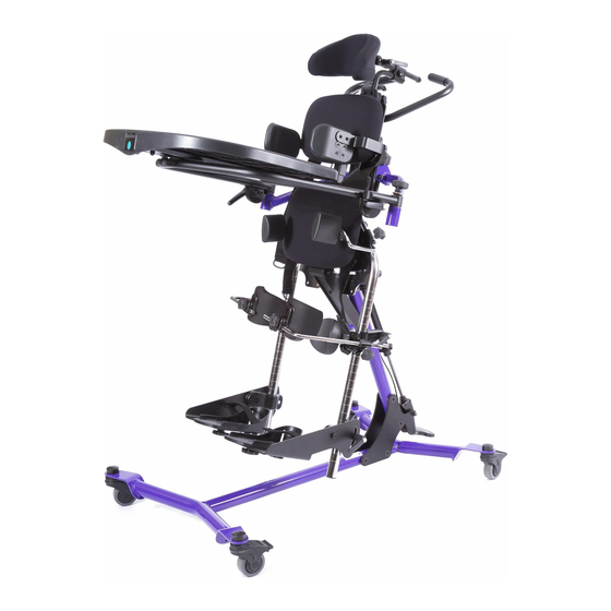
- Page 1 size2 Owner’s Manual Please ensure the Owner’s Manual stays with the unit at all times.
- Page 2 SYMBOL LEGEND ENVIRONMENTAL CAUTION/ATTENTION CONDITIONS TYPE BF APPLIED PART DATE OF MANUFACTURE SEE INSTRUCTIONS FOR USE PINCHPOINT MANUFACTURER SERIAL NUMBER Please be environmentally responsible and recycle this product through your recycling facility at its end of life. Afin de préserver l’environnement, veuillez confier ce produit à votre centre de recyclage à la fin de sa durée de vie.
-
Page 3: Table Of Contents
Table of Contents Introduction . . . . . . . . . . . . . . . . . . . . . . . . . . . . . . . . . . 1 Safety Precautions . -
Page 4: Introduction
Various support and positioning options may be added to facilitate individual needs. Indications for Use The Zing Size 2 is indicated for most individuals weighing up to 154 lbs. and within the height range of 40 to 60 inches. Intended Use The EasyStand Zing products have a manual or electrically operated flat surface (electric option offered on Zing Size 2 only) that can be adjusted to various positions (i.e. -
Page 5: Safety Precautions
• If the EasyStand is being used in the home environment, please inspect the unit prior to each use to ensure there is no damage or unexpected wear to the EasyStand that may have been caused unintentionally by pets, pests or children. -
Page 6: Assembly
Assembly 1. Remove everything from the box. Remove all plastic wrap and parts from the boxes. 2. Remove the bag of hardware from the wheelbase. It contains the 4 bolts for the mast assembly. 3. Position the mast as shown, place the wheelbase as shown onto the mast. - Page 7 4A. Start all 4 bolts. Do not tighten at this time. 4B. Once all 4 bolts have been started, tighten them securely. 5. Remove the wrapping and bolts from the foot pedal and place the foot pedal onto the bottom of the gas spring as shown. 6.
- Page 8 7. Place unit onto its wheels as shown, and lock casters. 8. If the Gas Spring Lockout was ordered, unlock the gas spring by pulling the plunger. (see page 33) If the Gas Spring Lockout was not ordered, remove the bolt from the lower part of the cylinder on the mast as shown, discard bolt.
- Page 9 10. Flip up the brace as shown. Bracket Brace 11. Depress the foot pedal to allow the mast to expand about 2 inches. For the Pow’r Up Lift, use the controller to allow the unit to expand about 2 inches. 12.
- Page 10 13. Insert bolt into the hole about halfway through the brace. 14A. Insert washer on the other side of the brace and line up holes. You may need to use a flat head screwdriver to assist with the opening. 14B. Insert the bolt all the way through the holes.
- Page 11 16. For the leg assembly, remove the two bolts behind the support pad. Set aside. 17. Place leg assembly onto unit as shown and line up holes. Making sure the ratchet handle and knee clamp are facing towards the rear of the unit. Insert both bolts and tighten securely.
- Page 12 If a Tilt Table (TT) model was ordered, skip to step 23. If a Prone model was ordered, skip to step 29. MPS and Supine 19. Loosen the knob on the upper body support. MPS and Supine 20. Place upper body support onto post as shown.
- Page 13 MPS and Supine 22. Loosen knob on head support bracket, insert head support and tighten knob securely. Tilt Table 23. If a Tilt Table (TT) model was ordered follow steps 23-27, remove the 6 bolts from the back of the upper body support pad. Tilt Table 24.
- Page 14 Tilt Table 25. Using a hex wrench, insert 2 lower bolts into the holes on the pad. Tighten snug. Note: Use the 2 holes on the bracket to access the lower holes in the pad. Tilt Table 26. Place head support/push handle bracket into support tube as shown.
- Page 15 Tilt Table 28A. If the optional chest strap was ordered, place it around the pad as shown. 28B. Position strap in the grooves on the support bracket as shown. Prone 29. If the Prone model was ordered follow steps 29-35, remove the cap on the support tube and discard.
- Page 16 Prone 31. Loosen knob and insert upper body support into the support tube and tighten knob securely. Tighten set screw. Prone 32. If the face aperture was ordered. Depress the spring button and place it onto the support tube. Prone 33.
- Page 17 Prone 34. Place the push handle for the tray onto the support brackets as shown. Prone 35A. Line up holes on support brackets 8 35B and push handle. Insert bolts and tighten securely. 35B. Repeat steps 33-35 for other side of tray.
- Page 18 MPS, Supine, TT 37. Loosen knobs on the tray brackets and flip open the gray latch all the way as shown below. MPS, Supine, TT 38. Lock the casters, insert the two tray arms into the tray bracket on the bottom of the tray as shown.
- Page 19 MPS, Supine, TT 40. Flip the tray arm as shown. MPS, Supine, TT 41. Place the ratchet handle that was sent with the manual onto the bolt and tighten securely. Repeat steps for the other side. MPS, Supine, TT 42. There are 2 knobs in the parts bag. Screw each knob slightly into the tray bracket on the unit.
- Page 20 Prone 43. If the Prone model was ordered. Loosen ratchet handles on the side of the tray. Flip tray support brackets up as shown. Tighten ratchet handles securely. Prone 44. Insert tray support brackets into the following tubes as shown. Depress spring button and place tray into desired position, tighten knobs securely.
- Page 21 46. If hip supports were ordered, loosen knob on the hip support bracket on the leg. Insert hip support as shown, tighten knob securely. Repeat steps for other hip support bracket. 47. If the multi-adjustable knee pads were ordered, loosen ratchet handles on the knee clamps.
- Page 22 MPS, Supine, TT Prone 49. If the multi-adjustable foot plates were ordered, loosen ratchet handle on foot plate, place foot plate bracket onto the leg as shown, place in desired position and tighten ratchet handle securely. Repeat steps for other foot plate. Platform Foot Plate Loosen knobs and place onto legs as shown.
- Page 23 MPS, Supine, TT 52. Guide cable up behind pad. Make sure to guide cable on the back side of the push handle. MPS, Supine, TT 53. Remove bolt from the controller handle, place controller handle onto the push handle as shown. Insert bolt through the hole and tighten to the controller handle.
- Page 24 Prone 55. If the dual control was ordered, remove bolt from the controller handle, place controller handle onto the push handle as shown. Insert bolt through hole and tighten to the controller handle. Prone 56. Guide the cable under the tray and use provided zip tie to secure the cable.
-
Page 25: Pow'r Up Lift
Pow’r Up Lift Option Usage Charging the Battery The EasyStand Zing Pow’r Up Lift uses two 12-volt sealed lead batteries rated at 2.9 amps each. An EasyStand Zing can be lifted approximately 100 times on one full battery charge. An audible alarm will sound when the battery is low. - Page 26 RF communications equipment and the EasyStand Zing . The EasyStand Zing is intended for use in an electromagnetic environment in which radiated RF disturbances are con- trolled. The customer or the user of the EasyStand Zing can help prevent electromagnetic interference by...
- Page 27 Guidance and Manufacturer’s Declaration - Electromagnetic Immunity The EasyStand Zing is intended for use in the electromagnetic environment specified below. The customer or the user of the EasyStand Zing should assure that it is used in such an environment. Immunity Test...
- Page 28 Guidance and Manufacturer’s Declaration - Electromagnetic Emissions The EasyStand Zing is intended for use in the electromagnetic environment specified below. The customer or the user of the EasyStand Zing should assure that it is used in such an environment. Compliance...
-
Page 29: Option Adjustments And Usage
Option Adjustments & Usage Trays Black Molded/Swing-Away Tray Height 58. To adjust tray height, loosen knobs on the back of unit and set to desired position. Tighten securely. Black Molded Tray Depth 59. To adjust the tray, loosen the knobs on each side until resistance is felt, then flip the gray lever in the center of the knob fully open. - Page 30 Hip Supports 64. The hip support width can be adjusted by loosening the knobs behind the pelvic pad. Adjust to desired position and tighten securely. 65. To adjust the fore/aft positioning on the hip supports, loosen the thumb knobs and put in desired position.
- Page 31 Calf Pad with Knee Strap 68. To adjust the calf pad with knee strap, loosen knobs on each side. Position fore/aft and up/down to the desired setting. Tighten securely. Multi-Adjustable Knee Pads 69. To adjust the multi-adjustable knee pad height, loosen the ratchet handle. Adjust to desired position.
- Page 32 Upper Body Support Pad 74. To adjust the upper body support pad height, loosen knob. 75. Depress spring button and adjust to desired position. Tighten knob securely. Head Support 76. To adjust the head support depth, loosen the knob on the back of the headrest and slide into desired position.
- Page 33 Leg Abduction 79. Loosen knob behind the pelvic pad. 80. Abduct each leg out to the desired position up to 30 degrees per leg. Tighten securely. Face Aperature 81. To adjust the aperature height, loosen the knob on the support bracket. Place into desired position and tighten securely.
- Page 34 Platform Foot Plates 83. Height-Platfrom Foot Plates are only height adjustable. Loosen knob, set to desired position. Tighten securely. 84A. Straps (if ordered)-Position straps into desired slots. 84B. Foot Holders-Position foot holders into desired position. Insert bolt and tighten knob securely.
- Page 35 Supine 91. Flip the lever located behind the pelvic pad to the “supine to stand” position. 92. Adjust to the desired supine position by depressing the foot pedal or using the hand pendant on the Pow’r Up option and tilting. This can be done with the user in the unit.
- Page 36 Gas Spring Lockout 97. Pull the lockout knob out and twist to unlock. Your unit can now be positioned using the foot pedal or hand lever. 98. Twist until the knob is vertical and locks into position. The gas spring is now locked from unintended movement.
-
Page 37: Parts Detail
Parts Detail- MPS Page 34... - Page 38 Parts Detail- Supine Page 35...
- Page 39 Parts Detail- TT MPS Page 36...
- Page 40 Parts Detail- TT Supine Page 37...
- Page 41 Parts Detail- Prone Page 38...
-
Page 42: Maintenance
Do not dry clean any upholstery items. • If the EasyStand is being used with one user, clean the EasyStand on a monthly basis or as needed. • If the EasyStand is being used in a multiple-user environment, the EasyStand should be cleaned after each use. -
Page 43: Limited Warranty
Limited Warranty This warranty is extended only to the original purchaser/customer (or supplier/non consumer who does not buy or resell). Altimate Medical, Inc., warrants the EasyStand against defects in materials and workmanship as listed below. • Steel Frames - 5 year warranty •...
Need help?
Do you have a question about the Zing and is the answer not in the manual?
Questions and answers