Table of Contents
Advertisement
Quick Links
Industrial
Lite-Managed Ethernet Switch
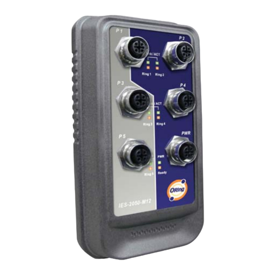
IES-2050-M12 User's Manual
Version 1.3
Feb, 2010
ORing Industrial Networking Corp.
4F., NO.3, Lane235, Baociao Rd.Sindian City,
Taipei County 23145 Taiwan, R.O.C.
Tel: + 886 2 2918 3036
Fax: + 886 2 2918 3084
Website: www.oring-networking.com
E-mail:
support@oring-networking.com
Advertisement
Table of Contents

Related Manuals for ORiNG IES-2050-M12


Summary of Contents for ORiNG IES-2050-M12
- Page 1 Industrial Lite-Managed Ethernet Switch IES-2050-M12 User’s Manual Version 1.3 Feb, 2010 ORing Industrial Networking Corp. 4F., NO.3, Lane235, Baociao Rd.Sindian City, Taipei County 23145 Taiwan, R.O.C. Tel: + 886 2 2918 3036 Fax: + 886 2 2918 3084 Website: www.oring-networking.com E-mail: support@oring-networking.com...
-
Page 2: Table Of Contents
Table of Content Getting to Know Your Switch................3 About the IES-2050-M12 Entry-Level Managed Industrial Switch ......3 Software Features ......................3 Hardware Features......................3 Hardware Installation..................4 Installing IES-2050-M12 on DIN-Rail................4 Wall Mounting Installation....................6 2.2.1 Mount IES-2050-M12 Series on wall ................6 Hardware Overview..................9 Front Panel ..........................9 Cables ......................10... - Page 3 SNMP –Trap Setting .....................26 5.1.6 VLAN ..........................27 5.1.6.1 VLAN Configuration – Port Based ...............27 5.1.7 Warning ..........................28 5.1.7.1 Fault Alarm ......................28 5.1.8 Front Panel........................32 5.1.9 Save Configuration ......................32 5.1.10 Factory Default ......................33 5.1.11 System Reboot ......................33 Technical Specifications ................34 ORing Industrial Networking Corp.
-
Page 4: Getting To Know Your Switch
The IES-2050-M12 switch is cost-effect and powerful industrial switch with many features. The switch can work under wide temperature and dusty environment and humid condition. The IES-2050-M12 switch can be managed by WEB and a useful Windows Utility we called Open-Vision. Open-Vision is powerful network management software. With its friendly and powerful interface, you can easily configure multiple switches at the same time, and monitor switches’... -
Page 5: Hardware Installation
Installation Installing IES-2050-M12 on DIN-Rail Each IES-2050-M12 switch has a DIN-Rail kit on rear panel. The DIN-Rail kit helps switch to fix on the DIN-Rail. It is easy to install the switch on the DIN-Rail: ORing Industrial Networking Corp. - Page 6 IES-2050-M12 User’s Manual Step 1: Slant the switch and mount the metal spring to DIN-Rail. Step 2: Push the switch toward the DIN-Rail until you heard a “click” sound. ORing Industrial Networking Corp.
-
Page 7: Wall Mounting Installation
Each switch has another installation method for users to fix the switch. A wall mount panel can be found in the package. The following steps show how to mount the switch on the wall: 2.2.1 Mount IES-2050-M12 on wall Step 1: Remove Din-Rail kit. - Page 8 Step 2: Use 3 screws that can be found in the package to combine the wall mount panel. Just like the picture shows below: The screws specification shows in the following two pictures. In order to prevent switch from any damage, the screws should not larger than the size that used in IES-2050-M12 switch. Pozidrive...
- Page 9 IES-2050-M12 User’s Manual Step 3: Mount the combined switch on the wall. ORing Industrial Networking Corp.
-
Page 10: Hardware Overview
IES-2050-M12 User’s Manual ardware Overview Front Panel The following table describes the labels that stick on the IES-2050-M12. Port Description 10/100Base-T(X) M12 Connector Ethernet ports support auto-negotiation. 10/100 Default Setting : M12 Connector Speed: auto Ethernet ports Duplex: auto Flow control : disable IES-2050-M12 1. -
Page 11: Cables
Ethernet Cables The IES-2050-M12 switch have standard Ethernet ports. According to the link type, the switch use CAT 3, 4, 5, 5e UTP cables to connect to any other network device (PCs, servers, switches, routers, or hubs). Please refer to the following table for cable specifications. -
Page 12: Web Management
IES-2050-M12 User’s Manual EB Management Configuration by Web Browser This section introduces the configuration by Web browser. 5.1.1 About Web-based Management An embedded HTML web site resides in flash memory on the CPU board. It contains advanced management features and allows you to manage the switch from anywhere on the network through a standard web browser such as Microsoft Internet Explorer. - Page 13 IES-2050-M12 User’s Manual 3. The login screen appears. 4. Key in the username and password. The default username and password is “admin”. 5. Click “Enter” or “OK” button, then the main interface of the Web-based management appears. Login screen Main Interface Main interface ORing Industrial Networking Corp.
-
Page 14: Basic Setting
IES-2050-M12 User’s Manual 5.1.2 Basic Setting 5.1.2.1 Switch setting Switch setting interface The following table describes the labels in this screen. Label Description Assign the name of switch. The maximum length is 64 bytes System Name Display the description of switch. -
Page 15: Ip Configuration
IES-2050-M12 User’s Manual Admin Password interface The following table describes the labels in this screen. Label Description Key in the new username (The default is “admin”) User name Key in the new password (The default is “admin”) New Password Re-type the new password. -
Page 16: Sntp Configuration
IES-2050-M12 User’s Manual client function is enabling, the switch will assign the IP address from the network DHCP server. The default IP address will be replaced by the IP address which the DHCP server has assigned. After clicking “Apply” button, a popup dialog will show up to inform you when the DHCP client is enabling. - Page 17 IES-2050-M12 User’s Manual The following table describes the labels in this screen. Label Description Enable or disable SNTP function to get the time from the SNTP SNTP Client server. Enable or disable daylight saving time function. When daylight Daylight Saving Time saving time is enabling, you need to configure the daylight saving time period.
- Page 18 IES-2050-M12 User’s Manual CET - Central European FWT - French Winter MET - Middle European +1 hour 1 pm MEWT - Middle European Winter SWT - Swedish Winter EET - Eastern European, USSR +2 hours 2 pm Zone 1 BT - Baghdad, USSR Zone 2...
-
Page 19: Lldp
IES-2050-M12 User’s Manual 5.1.2.5 LLDP LLDP (Link Layer Discovery Protocol) function allows the switch to advertise its information to other nodes on the network and store the information it discovers. LLDP interface The following table describes the labels in this screen. -
Page 20: Upgrade Firmware
IES-2050-M12 User’s Manual The following table describes the labels in this screen. Label Description Fill in the TFTP server IP TFTP Server IP Address Fill the file name. Restore File Name Click “restore” to restore the configurations. Restore Fill the file name. -
Page 21: Port Configuration
IES-2050-M12 User’s Manual 5.1.3 Port Configuration 5.1.3.1 Port Control By this function, you can set the state, speed/duplex, flow control, and security of the port. Port Control interface The following table describes the labels in this screen. Label Description Port number for setting. -
Page 22: Redundancy
The Fast Recovery Mode can be set to connect multiple ports to one or more switches. The IES-2050-M12 with its fast recovery mode will provide redundant links. Fast Recovery mode supports 4 priorities, only the first priority will be the act port, the other ports configured with other priority will be the backup ports. - Page 23 IES-2050-M12 User’s Manual O-Ring interface The following table describes the labels in this screen. Label Description Mark to enable O-Ring. O-Ring There should be one and only one Ring Master in a ring. Ring Master However if there are two or more switches which set Ring Master to enable, the switch with the lowest MAC address will be the actual Ring Master and others will be Backup Masters.
-
Page 24: Rstp
IES-2050-M12 User’s Manual 5.1.4.3 RSTP The Rapid Spanning Tree Protocol (RSTP) is an evolution of the Spanning Tree Protocol. It provides faster spanning tree convergence after a topology change. The system also supports STP and the system will auto detect the connected device that is running STP or RSTP protocol. - Page 25 IES-2050-M12 User’s Manual must be multiple of 4096 according to the protocol standard rule. The number of seconds a bridge waits without receiving Max Age (6-40) Spanning-tree Protocol configuration messages before attempting a reconfiguration. Enter a value between 6 through 40.
-
Page 26: Snmp Configuration
IES-2050-M12 User’s Manual RSTP Information interface 5.1.5 SNMP Configuration Simple Network Management Protocol (SNMP) is the protocol developed to manage nodes (servers, workstations, routers, switches and hubs etc.) on an IP network. SNMP enables network administrators to manage network performance, find and solve network problems, and plan for network growth. -
Page 27: Snmp -Trap Setting
IES-2050-M12 User’s Manual The following table describes the labels in this screen. Label Description SNMP Community should be set for SNMP. Four sets of SNMP – Agent "Community String/Privilege" are supported. Each Community Setting String is maximum 32 characters. Keep empty to remove this Community string. -
Page 28: Vlan
IES-2050-M12 User’s Manual 5.1.6 VLAN A Virtual LAN (VLAN) is a logical network grouping that limits the broadcast domain, which allows you to isolate network traffic. Only the members of the VLAN will receive traffic from the same members of VLAN. Basically, creating a VLAN from a switch is logically equivalent of reconnecting a group of network devices to another Layer 2 switch. -
Page 29: Warning
IES-2050-M12 User’s Manual 5.1.7 Warning Warning function is very important for managing switch. You can manage switch by SYSLOG, E-MAIL, and Fault Relay. It helps you to monitor the switch status on remote site. When events occurred, the warning message will send to your appointed server, E-MAIL, or relay fault to switch panel. - Page 30 IES-2050-M12 User’s Manual System event log interface The following table describes the labels in this screen. Label Description Select LOG page. Page To get the newest event logs and refresh this page. Reload Clear log. Clear Show help file. Help System Warning –...
- Page 31 IES-2050-M12 User’s Manual System Warning – SMTP Setting interface The following table describes the labels in this screen. Label Description Enable/Disable transmission system warning events by e-mail. E-mail Alarm The SMTP server IP address Sender E-mail Address The Subject of the mail Mail Subject Username: the authentication username.
- Page 32 IES-2050-M12 User’s Manual System Warning – Event Selection interface The following table describes the labels in this screen. Label Description System Event Alert when system restart System Cold Start Alert when O-Ring topology change O-Ring Topology Change Port Event Disable...
-
Page 33: Front Panel
IES-2050-M12 User’s Manual 5.1.8 Front Panel Show IES-2050-M12 panel. Click “Close” to close panel on web. Front panel interface 5.1.9 Save Configuration If any configuration changed, “Save Configuration” should be clicked to save current configuration data into the permanent flash memory. Otherwise, the current configuration will be lost when power off or system reset. -
Page 34: Factory Default
IES-2050-M12 User’s Manual 5.1.10 Factory Default Factory Default interface Reset switch to default configuration. Click Reset to reset all configurations to the default value. You can select “Keep current IP address setting” and “Keep current username & password” to prevent IP and username & password from default. -
Page 35: Technical Specifications
IES-2050-M12 User’s Manual echnical Specifications Technology Ethernet Standards IEEE802.3 10BASE-T IEEE802.3u 100BASE-TX IEEE802.3x Flow Control and Back pressure IEEE802.1D Spanning tree protocol IEEE802.1w Rapid Spanning tree protocol IEEE802.1AB LLDP MAC addresses 2048 Flow Control IEEE 802.3x Flow Control and Back-pressure... - Page 36 IES-2050-M12 User’s Manual Mechanical Dimensions(W x D x H) 90 mm(W) x 40.5 mm(D) x 155 mm(H) Casing IP-67 protection Regulatory Approvals Regulatory Approvals FCC Part 15, CISPER (EN55022) class A EN61000-4-2 (ESD), EN61000-4-3 (RS), EN61000-4-4 (EFT), EN61000-4-5 (Surge), EN61000-4-6 (CS)
Need help?
Do you have a question about the IES-2050-M12 and is the answer not in the manual?
Questions and answers