Advertisement
Quick Links
Advertisement

Subscribe to Our Youtube Channel
Related Manuals for NI Climbing Frames The Gardensmith


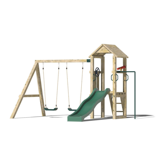
Summary of Contents for NI Climbing Frames The Gardensmith
- Page 1 The Gardensmith Instruction Manual...
- Page 2 Parts List Item Description Image Quantity Number 2.4m post cut at 40° angle 720mm post 900mm x 3” x 1.5” 720mm x 3” x 1.5”...
- Page 3 900mm x 650mm roof panel 6” x 1” small board for roof 6” x 1” large board for roof 850mm x 6” x 1” 900mm decking boards...
- Page 4 Steps Slide Decking screws 200mm index screws...
- Page 5 120mm screws Grab Handles Screw covers Telescope...
- Page 6 Steering Wheel Fireman’s Pole 6 x 60 screws...
- Page 7 720mm x 3” x 3” Post 2.6m Cut at 60° Angle (A-Frame) 2100mm Swing Beam...
- Page 8 1460mm x 3” x 1.5” Square Wall Bracket M10 Swing Hooks...
- Page 9 Swings Tools needed: • Cordless drill • Handsaw • Spirit Level • Hammer • Shovel • Stepladder • Pencil • Measuring tape • 10mm Hex bit • PZ 2 Drill Bit...
- Page 10 Assembly Instructions All components needed during the assembly are numbered with reference to the parts list, please refer back to the parts list to ensure you are assembling the correct components for each step. Step 1: ‘H-Frame’ Assembly • Lay 2 x 2.4m posts that are cut at a 40° angle on a level surface •...
- Page 11 Step 3: • Make a mark 1800mm (1.8m) from the top of both 2.4m posts. • Using a piece of 900mm 3” x 1.5” timber and the 65mm decking screws, screw the timber to the 2.4m posts at the 1.8m mark you made on the posts (this is to strengthen the H-frame structure, without this additional support at the bottom the frame will twist once it is lifted •...
- Page 12 Step 4: • Place another 900mm 3” x 1.5” timber on the 40° angle on the top of the post and screw into place using the 65mm decking screws • Steps 3 and 4 strengthen the H-frame structure, without this additional support at the top and bottom, the frame will twist once it is lifted up...
- Page 13 Step 5: • Repeat steps 1-4 for the 2 H-frame Step 6: (Requires heavy lifting, please use at least 2 people) • Dig holes in the grass in the position that you want the climbing frame to be placed with a diameter of approx.
- Page 14 Step 7: • Using 2 pieces of 720mm x 3” x 1.5” timber, connect the two H-frames together using decking screws • These pieces of timber will also be removed at the end of the installation...
- Page 15 Step 8: Base Assembly • Create the base using 3 x 900mm x 3” x 1.5” and the decking boards. Two of the decking boards should be cut out at the corners to fit around the posts. Secure the other decking boards in between them and this should give you a 900mm x 900mm base.
- Page 16 Step 9: Securing the Base to the Tower • The structure should now be able to stand on its own • Lift the base and place it onto the two horizontal posts. The 3” x 1.5” base supports should sit onto the horizontal posts •...
- Page 17 Step 10: Roof Assembly • Place one of the 950mm x 650mm roof panels directly onto the ground (so that the shingled part is facing downwards) • Using the ‘v’ boards provided assemble the two roof panels together using decking screws...
- Page 18 Step 11: • Lift the roof onto the climbing frame and ensure it is positioned evenly on all sides before securing the roof to the top of the post using 2 x decking screws for each 2” x 1” support of the roof panel •...
- Page 19 Step 12: Steps Assembly • The steps might have to be cut or dug into place (depending on the slope of your surface) • They are secured using decking screws through the top and sides of the steps into the base of the tower.
- Page 20 Step 13: Slide Assembly • Secure a piece of 720mm x 3” x 1.5” to the front of the base using decking screws, the slide will be secured to this. • Using two 6 x 60 screws, secure the slide to the 720mm x 3” x 1.5” through the pre-drilled holes in the slide...
- Page 22 Step 14: Railings Assembly • Secure a piece of 900mm x 3” x 1.5” to the outside of two upright posts, the 3” x 1.5” should be level with the 720mm post that the base is secured to. • Secure another 900mm x 3” x 1.5”to the posts, ensure there is 850mm between the timbers so the 850mm x 6”...
- Page 23 Step 15: Railings Assembly • Secure the 3 pieces of 850mm x 6” x 1” boards to the timbers secured in the last step using decking screws.
- Page 24 Step 16: Railings Assembly • On the other side of the tower, secure the 720mm x 3” x 3” post using 200mm index screws at the height you want the fireman’s pole to be at. You will need to drill 32mm holes on the outside of the posts approx.
- Page 25 Step 17: Fireman’s Pole Assembly • Place the fireman’s pole into its position and mark the position that it will go into the ground, which will be the centre of the 720mm x 3” x 3” post and out the same distance as the turn in the pole itself •...
- Page 26 Step 18: Swing Module Assembly • Lay the 2 x 2.6m posts (with the ends cut off at 60 degrees) on a flat surface • Place the ends together so that it forms an A-shape • Using the 200mm index screws, screw the ends together, so the two posts meet nice and flush on all sides...
- Page 27 Step 19: • Measure down from the top of the ‘A’ post 900mm to both posts and place the 1460mm 3” x 1.5” timber across both posts and secure these into place with decking screws • Cut the 1460mm 3” x 1.5” timber so that it is flush on both sides of the A-frame Step 20: •...
- Page 28 Step 21: (Two People needed for this step) • Mark the positions of the holes for the A-frame by using the 2100mm swing beam as guide and dig the holes 300mm in diameter and 300mm deep • Secure the square wall bracket to the top of the post and secure the swing beam to the bracket using 6 x 60 screws •...
- Page 29 Step 22: • Hang your swings from the swing hooks...
- Page 30 Step 23: • Add the telescope, steering wheel and grab handles using the fixings supplied and press the screw covers in all the 32mm holes. Step 24: Concreting structure • Using postcrete and following the manufacturer’s instructions, concrete all the posts into the ground •...
- Page 31 Step 25: Removing the H-Frame supports • Remove the lower H-Frame supports that were added during steps 3 and 7.
- Page 32 The final stage is to give everything a good sand down to avoid the children getting splinters from any rough edges. All screws should also be checked to ensure they are flush to the surface they are securing.
- Page 33 Maintaining Your Climbing Frame My climbing frame has been installed, what do I do next? A: If your climbing frame was installed in a grassed area the installers have concreted the frame into the ground. They have left a small exposed hole, where the posts have been sunk into the ground. The reason this has been done is to allow the concrete to set overnight.
Need help?
Do you have a question about the The Gardensmith and is the answer not in the manual?
Questions and answers