
Related Manuals for Veilux VP-36X


Summary of Contents for Veilux VP-36X
- Page 1 ’ ’ Website: www.Veilux.net Phone # 1-800-510-6528 Rev.1.0 (Nov. 2010)
- Page 2 ’ ’ Copyright ⓒ 2010 Veilux. Certification Veilux provides the best products with the certifications below Revision History Date Rev. No. Description 2010-06 Creation of the document 2010-11 Image Change, Detailed Specification Change, Appendix Website: www.Veilux.net Phone # 1-800-510-6528 Rev.1.0 (Nov. 2010)
- Page 3 Never use the product in extremely high or low temperature condition. Never drop, hit, strongly nor vibrate the product. Never expose the product to direct sunlight or severe ray. Never touch the front glass of the product. Website: www.Veilux.net Phone # 1-800-510-6528 Rev.1.0 (Nov. 2010)
- Page 4 ’ ’ Indications: Warning: Death or Serious Injury will occur without following Warning. Caution : Operational Problem(Faulty & Malfunction) will occur without complying with Caution Reference : Technical Information for Users Website: www.Veilux.net Phone # 1-800-510-6528 Rev.1.0 (Nov. 2010)
-
Page 5: Table Of Contents
’ ’ Table of Contents Table of Contents ................5 1. Introduction ................... 7 1.1. Overview of Veilux VP-36X ................7 1.2. Specification ....................8 1.3. Application of Veilux VP-36X ............... 10 2. Product Description............... 11 2.1. Contents ....................11 2.2. - Page 6 ’ ’ Appendix. OSD Menu setting ............38 Website: www.Veilux.net Phone # 1-800-510-6528 Rev.1.0 (Nov. 2010)
-
Page 7: Introduction
IP Network as well as supports bi-directional audio communication by allowing transmission of audio from Client PC to Veilux VP-36X. Veilux VP-36X, with completed Integration with analog CCTV camera, Digital and network technology, is applicable for various sectors such as Security, Remote Monitoring, Remote Education, Simple Video Conference as well as Internet Broadcasting System etc. -
Page 8: Specification
CMS Software Viewer 3rd Party CMS Contact to Veilux Dynamic IP DDNS support Supported by Veilux Management Server User ID & Password Protection, IP Filtering, Audio per user Security Management and Bi-directional audio communication configuration control Time Sync to PC... - Page 9 811 (H) * 508 (V) 410K No. of Pixels Camera 795 (H) * 596 (V) 470K Module No. of NTSC 811 (H) * 508 (V) 410K Effective 795 (H) * 596 (V) 470K Pixels Website: www.Veilux.net Phone # 1-800-510-6528 Rev.1.0 (Nov. 2010)
-
Page 10: Application Of Veilux Vp-36X
Security surveillance (buildings, stores, manufacturing facilities, parking lots, banks, government facilities, military, etc.) Remote monitoring (hospitals, kindergartens, traffic, public areas, etc.) Teleconference (Bi-directional audio conference). Remote Learning, Internet broadcasting Weather and Environmental Observation Website: www.Veilux.net Phone # 1-800-510-6528 Rev.1.0 (Nov. 2010) -
Page 11: Product Description
’ ’ 2. Product Description The product package contains followings; Contents Description Remarks Veilux VP-36X Veilux VP-36X Main Unit Power Adaptor 24V AC Adaptor Software & User’s Guide Quick Reference Quick Installation Guide CMS Software Veilux VP-36X IP-Installer (NVXR-64) PC based Client for H.264 Professional Speed... -
Page 12: Physical Description
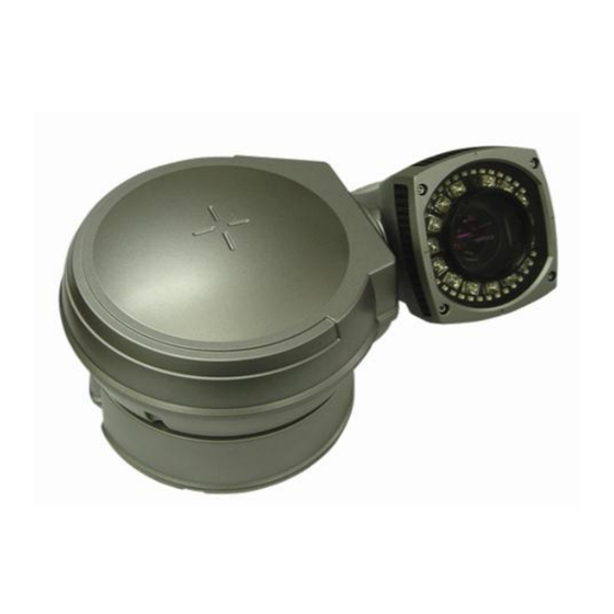
’ ’ 2.3.1. External View Figure 2-1. External View of Veilux VP-36X Website: www.Veilux.net Phone # 1-800-510-6528 Rev.1.0 (Nov. 2010) -
Page 13: Internal Structure
’ ’ Figure 2-2. Cabling Description Website: www.Veilux.net Phone # 1-800-510-6528 Rev.1.0 (Nov. 2010) -
Page 14: Dimension
Power Input for supplying 24V AC, 1.5A. MIC/LINE IN Connect external Audio Device or Microphone. Line Out Connect speakers with built in amplifier. Audio from remote site is output through Line out in bi-directional audio mode. Website: www.Veilux.net Phone # 1-800-510-6528 Rev.1.0 (Nov. 2010) - Page 15 ’ 100Base-T 100Mbps Ethernet connector (RJ-45). 2 LEDs on the Ethernet connector shows the status of Veilux VP- 36X as the followings: Status LED (Dual Color - Red/Green) : It will be lit in green or red depending on the status.
- Page 16 10 mA can be flown into sensor device. Multiple sensor devices can be connected in parallel. Photo Coupler NO/NCType Open CollectorType Sensor1+ Sensor Sensor Device Device Sensor1- +12V Sensor Sensor Power Power Supply Supply Figure 2-4. Sensor Input Connection Diagram Website: www.Veilux.net Phone # 1-800-510-6528 Rev.1.0 (Nov. 2010)
-
Page 17: On Site Installation
3. Connect the Safety wire of the Camera to the Bracket. In order to avoid getting entangled in the Camera, fasten the Safety wire to the bracket with Cable tie. SAFETY WIRE SCREW (M4*15 4EA) CABLE TIE SPRING WASHER (∮4 4EA) Figure 3-2. Connection of Camera & Bracket Website: www.Veilux.net Phone # 1-800-510-6528 Rev.1.0 (Nov. 2010) - Page 18 Figure 3-3. Ceiling Mount 5. Install 4 pieces of Anchor bolt in the holes at the edge and tight enough with NUTs. Website: www.Veilux.net Phone # 1-800-510-6528 Rev.1.0 (Nov. 2010)
-
Page 19: Wall Mount
Figure 3-4. Hole Position & Size Install the Veilux VP-36X at the high place out of hands in order to protect the product safely. 2. Connect the Camera to Wall Mount Bracket with 4 pieces of M4*15 screws and Spring Washer. - Page 20 4. With Wall Mount Installation, Connection in the Bracket through Wall and Connection out of the Bracket on the Wall are available. Refer to Figure3-6. 5. Install 4 pieces of Anchor bolt in the holes at the edge and tight enough with NUTs. Website: www.Veilux.net Phone # 1-800-510-6528 Rev.1.0 (Nov. 2010)
-
Page 21: Getting Started
Above ATI Chipset based 64M 1600x1200(UXGA) LAN Card Above 100Mbps Windows XP/ Vista/ 7 (32 Bit Only) Web Browser Above Internet Explorer 6.0 * Compliant OS: Windows 2000 professional / XP / Vista / 7 Website: www.Veilux.net Phone # 1-800-510-6528 Rev.1.0 (Nov. 2010) -
Page 22: Quick Installation Guide
Run the CD and Install IP Installer included in CD. Once install IP Installer, “WinPcap” will be installed. If not install “WinPCap”, IP Installer won’t operate. For the Network Configuration of Veilux VP-36X, IP Installer should be higher than 3.0.1 Version. - Page 23 Insert mgmt.net-video.net in ⑦ > Please configure to be registered on DDNS by marking Check Box. You can use after Member Registration on Management Site http://www.net-video.net/. 3. Remote Connection to IP Camera Connection via Web Viewer Website: www.Veilux.net Phone # 1-800-510-6528 Rev.1.0 (Nov. 2010)
- Page 24 If internet access is available, you can download it by accessing Camera or if you install NVR- Pro, Active-X module will be installed together. Connection to Admin Page Basic Control Video Crop Control Website: www.Veilux.net Phone # 1-800-510-6528 Rev.1.0 (Nov. 2010)
- Page 25 ’ ’ Figure 4-2. Connection via Web Viewer Basic ID / Password of Admin Tool : root / admin Website: www.Veilux.net Phone # 1-800-510-6528 Rev.1.0 (Nov. 2010)
- Page 26 4. Initial Configuration by connecting Admin Mode All Parameters of Veilux VP-36X are initially set as factory default. So you must change them with appropriate value to your network configuration by accessing via Admin Tool. Admin Tool Access Method is as below.
-
Page 27: Trouble Shooting
Please re-try to access or refer to other trouble shooting category. ( - If you get the response such as “Request timed out”, Network Configuration & Connection Status is in problem. Please check the Network Cable and Configuration. ( Website: www.Veilux.net Phone # 1-800-510-6528 Rev.1.0 (Nov. 2010) -
Page 28: Windows Vista & Windows 7 User
1) Select “NVXR-64” icon on the wallpaper. 2) Select “Properties” menu popped up by clicking right button on Mouse. 3) Select Check Box of “Run this program as an administrator” from the compatibility Tap. Website: www.Veilux.net Phone # 1-800-510-6528 Rev.1.0 (Nov. 2010) - Page 29 ’ Windows 7 Configuration 1. User Account Configuration 1) Select “User Account” on Control Panel 2) Select “Change User Account Control Setting” 3) Set the Alarm Level at the lowest “Never Notify” Website: www.Veilux.net Phone # 1-800-510-6528 Rev.1.0 (Nov. 2010)
- Page 30 1) Select “NVXR-64” icon on the wallpaper 2) Select “Properties” menu popped up by clicking right button on Mouse 3) Select Check Box of “Run this program as an administrator” from the compatibility Tap. Website: www.Veilux.net Phone # 1-800-510-6528 Rev.1.0 (Nov. 2010)
-
Page 31: Technical Inquiry
Please contact to your supplier if you still have problem even taking all trouble shootings. For the quickest solution, please prepare all information below; 1. Product Model Name 2. Serial No. & Mac Address 3. Date of Purchase 4. Summary of Problem 5. Error Message Website: www.Veilux.net Phone # 1-800-510-6528 Rev.1.0 (Nov. 2010) -
Page 32: Appendix. Dip Switch Configuration
00001100 11101010 01010000 10001100 00011010 11010000 01001100 10011010 00110000 11001100 01011010 10110000 00101100 11011010 01110000 10101100 00111010 11110000 01101100 10111010 00001000 11101100 01111010 10001000 00011100 11111010 01001000 10011100 00000110 11001000 01011100 10000110 Website: www.Veilux.net Phone # 1-800-510-6528 Rev.1.0 (Nov. 2010) - Page 33 00010101 01101011 11011110 10010101 11101011 00111110 01010101 00011011 10111110 11010101 10011011 01111110 00110101 01011011 11111110 10110101 11011011 00000001 01110101 00111011 10000001 11110101 10111011 01000001 00001101 01111011 11000001 10001101 11111011 00100001 01001101 00000111 Website: www.Veilux.net Phone # 1-800-510-6528 Rev.1.0 (Nov. 2010)
- Page 34 11100011 10101111 01011001 00010011 01101111 11011001 10010011 11101111 00111001 01010011 00011111 10111001 11010011 10011111 01111001 00110011 01011111 11111001 10110011 11011111 00000101 01110011 00111111 10000101 11110011 10111111 01000101 00001011 01111111 11000101 10001011 11111111 Website: www.Veilux.net Phone # 1-800-510-6528 Rev.1.0 (Nov. 2010)
- Page 35 Switch of DIP Switch 2, changeable speed is 4800bps, 9600bps. Factory Default Value : 2400bps. DIP SW2-7 DIP SW2-8 BAUD RATE 2400bps 4800bps 9600bps Not Used * The 2 of DIP Switch 2 are not used. Website: www.Veilux.net Phone # 1-800-510-6528 Rev.1.0 (Nov. 2010)
-
Page 36: Appendix. Quick Operating Keys
Appendix. Quick Operating Keys The Veilux VP-36X supports Pelco D / P Protocols. The default setting of the Veilux VP-36X is Pelco D / P (auto detection) with 2400bps (baud rate). [PELCO D/P Protocols] The comprehensive feature set of the camera is available from Pelco compatible controllers via quick operation keys as defined below. - Page 37 *This feature is operated by preset number but not included in OSD main menu. * Due to Zoom camera module. OSD menu not provides every feature. In this case, “Not available” is displayed on the monitor. Website: www.Veilux.net Phone # 1-800-510-6528 Rev.1.0 (Nov. 2010)
- Page 38 ’ ’ Appendix. OSD Menu setting OSD MENU TABLE Website: www.Veilux.net Phone # 1-800-510-6528 Rev.1.0 (Nov. 2010)
- Page 39 ENABLE/DISABLE. The default setting is DISABLE Mode and this feature is working as 97 + preset button. B-6. Dome Setup - LANGUAGE Multiple languages are selectable here including English, Italian and Polish. Move joystick to the right or left direction to select language. The default setting is ENGLISH. Website: www.Veilux.net Phone # 1-800-510-6528 Rev.1.0 (Nov. 2010)
- Page 40 To enter this page for set a password, move joystick to the right direction. The password is must set by preset number from 001 to 255 . The default setting is BLANK. Website: www.Veilux.net Phone # 1-800-510-6528 Rev.1.0 (Nov. 2010)
- Page 41 * If you set a password, you must ensure that it does not get lost. If you lost it, the dome must be returned for workshop repair. B-7-4. Dome Setup – [NEXT PAGE] – [OSD DISPLAY] The camera ID setting defines whether the camera OSD display is displayed or switched off. Website: www.Veilux.net Phone # 1-800-510-6528 Rev.1.0 (Nov. 2010)
- Page 42 B-7-6. Dome Setup – [NEXT PAGE] – [INITIALIZATION] To clear all memorized data for tour, preset, sector, privacy or pattern, move joystick to the right direction when the cursor is on [INITIALIZATION] Website: www.Veilux.net Phone # 1-800-510-6528 Rev.1.0 (Nov. 2010)
- Page 43 B-9. Dome Setup – [NEXT PAGE] – EXIT In order not to save any data and wants to escape this page, move joystick to the right direction when cursor is at EXIT Website: www.Veilux.net Phone # 1-800-510-6528 Rev.1.0 (Nov. 2010)
- Page 44 C-6. CAMERA SET – PIC FLIP Picture flip feature provides the opposite picture image in horizontally. Move joystick to the right or left direction to select OFF/ON. The default setting is OFF. Website: www.Veilux.net Phone # 1-800-510-6528 Rev.1.0 (Nov. 2010)
- Page 45 Joystick(Off, 1~5). The default setting is OFF. C-12. CAMERA SET – [NEXT PAGE] – IS MODE It help to stabilized video image when camera revealed to wind or other environmental reasons. The default setting is OFF. Website: www.Veilux.net Phone # 1-800-510-6528 Rev.1.0 (Nov. 2010)
- Page 46 Move joystick to the right direction when the cursor is at SAVE for saving the memorized preset data and ID then the cursor is located on Preset ID for the continuous preset No. setting. D-5. PRESET – EXIT To escape this page, move joystick to the right direction. Website: www.Veilux.net Phone # 1-800-510-6528 Rev.1.0 (Nov. 2010)
- Page 47 To select dwell time, move joystick to the left or right direction in order to adjust dwell time. Possible to set from 01 second to 99 seconds and the default setting is 03 seconds. Website: www.Veilux.net Phone # 1-800-510-6528 Rev.1.0 (Nov. 2010)
- Page 48 F-3. TOUR SET – TOUR STEP Each tour group is consisting up to 60 preset steps with different dwell time and speed. Possibly to match any preset # for each tour step. Website: www.Veilux.net Phone # 1-800-510-6528 Rev.1.0 (Nov. 2010)
- Page 49 Move joystick to the right or left direction to set as ON in order to show the selectable block in the central of the monitor. This block is appearing as a translucency square with blue color after set ON. The default setting is OFF. Website: www.Veilux.net Phone # 1-800-510-6528 Rev.1.0 (Nov. 2010)
- Page 50 H. PATTERN SET 8 programmable patterns are available with 16 characters of title. After set the data to the each pattern # 1~8, 81~88+ preset buttons are working as Pattern # 1~8. Website: www.Veilux.net Phone # 1-800-510-6528 Rev.1.0 (Nov. 2010)
- Page 51 4 Alarm inputs are available and each alarm is activating to presets, group tours or patterns. I-1. ALARM SET – ALARM NO. Up to 4 alarms are selectable using joystick to the right direction when cursor is on ALARM NO. Website: www.Veilux.net Phone # 1-800-510-6528 Rev.1.0 (Nov. 2010)
- Page 52 16) J. SECTOR SET Up to 8 programmable sectors are available with 16 characters. This feature is useful to memory the certain location such as parking zone or so on. Website: www.Veilux.net Phone # 1-800-510-6528 Rev.1.0 (Nov. 2010)
- Page 53 To escape this page, move joystick to the right direction K. EXIT To escape OSD Main Menu, move joystick to the right or left direction then this camera is ready to operate. Website: www.Veilux.net Phone # 1-800-510-6528 Rev.1.0 (Nov. 2010)
Need help?
Do you have a question about the VP-36X and is the answer not in the manual?
Questions and answers