Table of Contents
Advertisement
Quick Links
Advertisement
Table of Contents

Related Manuals for Veilux VPIP-D110X


Summary of Contents for Veilux VPIP-D110X
- Page 1 Veilux VPIP-D110X / VPIPI-D110X User’s Guide Rev2.2(Sep.2009)
- Page 2 Veilux VPIP-D110X / VPIPI-D110X User’s Guide Website: www.Veilux.net Phone # 1-800-510-6528 (April 2011)
- Page 3 Use only the AC power adapter which conforms to the specification in data sheet or optionally provided AC power adapter with the Veilux VPIP-D110X / VPIPI-D110X. If you would like to use the Veilux VPIP-D110X / VPIPI-D110X for security, monitoring, please check the legal regulations within the country.
- Page 4 Veilux VPIP-D110X / VPIPI-D110X User’s Guide Warning & Caution If you fail to read this information and handle the product incorrectly, death or serious injury may occur. The unit should be installed by trained personnel. Always stop using when the product emits smoke or abnormal heat.
- Page 5 Veilux VPIP-D110X / VPIPI-D110X User’s Guide Revision History Date Rev. No Description 2006-12-06 Creation of the document 2009-09-09 Revision of the Dip Switch and Specification. 2009-09-22 Revision of the wall bracket Website: www.Veilux.net Phone # 1-800-510-6528 (April 2011)
-
Page 6: Table Of Contents
5.1. Log On ..........................26 5.2. Basic Setup ........................28 5.3. Network Configuration ..................... 30 5.4. Wireless Configuration (This is not applicable to Veilux VPIP-D110X / VPIPI-D110X network camera) ..................Error! Bookmark not defined. 5.5. User Admin & Time Setup ....................33 5.6. - Page 7 Veilux VPIP-D110X / VPIPI-D110X User’s Guide Appendix 1. On Site Installation of Veilux VPIPI-D110X ..................59 Appendix 2. On Site Installation of Veilux VPIPI-D110X ..................64 Appendix 3. DIP Switch Setting ..........................73 Website: www.Veilux.net Phone # 1-800-510-6528 (April 2011)
-
Page 8: Introduction
VPIP-D110X / VPIPI-D110X can be connected, controlled and monitored from a remote location through an IP connection over internet or intranet. Unlike CCTV or DVR, the Veilux VPIP-D110X / VPIPI-D110X is easy to install and owner will experience cost and space savings in the installation owing to the state of the art technologies embedded in the system. - Page 9 Remote administration control Entire operational parameter set up, Software upgrade Various Mounting Brackets(optional) Wall, Pipe, Gooseneck mounting brackets Corner mount adaptor, Pole mount adaptor Built-in Fan / Heater(Veilux VPIP-D110X Only) Website: www.Veilux.net Phone # 1-800-510-6528 (April 2011)
- Page 10 Veilux VPIP-D110X / VPIPI-D110X User’s Guide Detailed Features of Speed Dome part World most silent speed dome camera Hot Keys This camera supports various hot key functions Adoption of timing belt, specialized gear, and other lo for ease of control by other controllers or DVRs.
-
Page 11: Applications Of Veilux Vpip-D110X / Vpipi-D110X
Veilux VPIP-D110X / VPIPI-D110X User’s Guide 1.3. Applications of Veilux VPIP-D110X / VPIPI-D110X IP surveillance (buildings, stores, manufacturing facilities, parking lots, banks, government facilities, military, etc., Real time Internet broadcasting Remote monitoring (hospitals, kindergartens, traffic, public areas, etc.,) ... -
Page 12: Product Description
Veilux VPIP-D110X / VPIPI-D110X User’s Guide 2. Product Description 2.1. Package Contents Open the package and check if you have the followings: Veilux VPIPI-D110X Veilux VPIP-D110X 1. Camera main body 1. All items of indoor speed dome net 2. CD(Manual, S/W) work camera 3. -
Page 13: Pc Requirements
2.3. PC Requirements AV streaming data received from Veilux VPIP-D110X / VPIPI-D110X can be decoded or stored in a PC running i- NVR program which is a viewing & recording program for a PC. Minimum requirement of the PC is described... - Page 14 . Connect 24 Volt AC adaptors to this terminal for supplying power to the network camera. AC adapter which is compliant to the specification for Veilux VPIP-D110X / AC24V VPIPI-D110X should be used. Misuse of power supply can cause damage to Veilux VPIP-D110X / VPIPI-D110X.
- Page 15 Veilux VPIP-D110X / VPIPI-D110X User’s Guide 2.4.2 Dimension and basic parts of Veilux VVIP-D110X / VPIPI-D110X A. Dimension A-1. Veilux VPIPI-D110X Fig 2.2 Dimension of Veilux VPIPI-D110X (unit : mm) A-2. i Veilux VPIP-D110X (Veilux VPIPI-D110X + Outdoor Housing) Fig.2-3 Dimension of Veilux VPIP-D110X Website: www.Veilux.net...
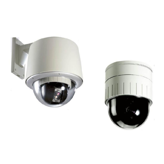
- Page 16 Veilux VPIP-D110X / VPIPI-D110X User’s Guide B. Exterior and Interior of View B-1.Common part of Veilux VPIP-D110X / VPIPI-D110X Fig.2-5 Common part of Veilux VPIP-D110X / VPIPI-D110X B-2.Outdoor Housing Website: www.Veilux.net Phone # 1-800-510-6528 (April 2011)
-
Page 17: Specification Of The Analog Camera Module And Ptz Part
Veilux VPIP-D110X / VPIPI-D110X User’s Guide Fig.2-6. Outdoor housing 2.5. Specification of the analog camera module and PTZ part 2.5.1. Zoom cameras Veilux VPIP-D110X / VPIPI-D110X are offered with 5 types of zoom camera modules as described in the following table. Camera module Lens Misc. - Page 18 Veilux VPIP-D110X / VPIPI-D110X User’s Guide Alarm Actions Activate preset, Group scanning or output per alarm input Aux Output 2 Replay Output Auto Flip ON / OFF OSD Menu Communication RS-485 Protocol Built in Pelco-D, Pelco-P Motor Type Stepping motor...
- Page 19 Veilux VPIP-D110X / VPIPI-D110X User’s Guide Night 0.01Lux 0.05Lux 0.02Lux 0.02Lux 0.01Lux 0.061Lux Mode Sens- up : 0.00007Lux 0.00007Lux 0.00007Lux 256x Luminance S/N More than 50dB Ratio Video Output Composite video output 75 ohm terminated ON / OFF Flickerless ON / OFF Website: www.Veilux.net...
-
Page 20: Quick Installation Guide
2.6. Quick Installation Guide Brief information for rapid installation is provided in this section. For more detailed information you are recommended to refer to pertinent documentations provided with the product or refer to Veilux‟s home page (http://www.Veilux.net) 1. Apply power to Veilux VPIP-D110X / VPIPI-D110X and Connect Veilux VPIP-D110X / VPIPI-D110X to LAN like the following picture. - Page 21 Input correct time in this field. Admin & Default value : Current Time Time 2001/1/1 Setup 5. Connect the input and output signals to Veilux VPIP-D110X / VPIPI-D110X. Connectors Function Signal description Number Connect microphone or output from audio Mic/LINE-In Audio/Voice in devices.
- Page 22 Apply AC24V power to network camera 6. Remote video connection to Veilux VPIP-D110X / VPIPI-D110X Run NVXR-64 on your PC. Before connecting to Veilux VPIP-D110X / VPIPI-D110X it is needed to configure the connection information on the NVXR-64. More detailed information of using “NVXR-64” can [NVXR-64 User‟s...
-
Page 23: Connecting Veilux Vpip-D110X / Vpipi-D110X To Ip Network
IP address for Veilux VPIP-D110X / VPIPI-D110X. 3.1. Connecting to LAN In case of connecting the Veilux VPIP-D110X / VPIPI-D110X to LAN, it is generally connected as in Fig. 3-1. Fig. 3-1 Connecting Veilux VPIP-D110X / VPIPI-D110X to LAN 1. -
Page 24: Connecting To Xdsl/Cable Modem
Please refer to the IP installer and i-NVR user‟s guide. 4. Connect Veilux VPIP-D110X / VPIPI-D110X with ADSL/Cable Modem as Fig.3.2 5. Run i-NVR program and check if you can receive video data when connecting to Veilux VPIP-D110X / VPIPI- D110X. -
Page 25: Ip-Installer
IP-Installer is a PC program for the initial network configuration to IP video products such as Network Camera or A/V Server. IP-Installer is provided in a CD supplied with Veilux VPIP-D110X / VPIPI-D110X or it can be downloaded from “www.Veilux.net”. -
Page 26: Configuring Veilux Vpip-D110X / Vpipi-D110X In Administrative Mode
5. Configuring Veilux VPIP-D110X / VPIPI-D110X in Administrative Mode 5.1. Log On There are 2 ways of connecting to Veilux VPIP-D110X / VPIPI-D110X administrative mode. One is through Internet Explorer and the other is through “NVXR-64” program. 1. Using Internet Explorer... - Page 27 Veilux VPIP-D110X / VPIPI-D110X User’s Guide Fig. 5-1 Main Screen of NVXR-64 3. Input User Name and Password in the display screen shown in Fig. 5-2. Fig. 5-2 Log On Screen Factory default User Name and Password are set as „root‟ and „dw2001‟, respectively. Click on “OK” button to enter into the Basic Setup page of Administrative Mode.
-
Page 28: Basic Setup
Description /Button Select a language of your choice Language Logical name of the Veilux VPIP-D110X / VPIPI-D110X. It is same as System Name the one set-up by IP-installer. You can reassign the system name. Select the type of input audio. - Page 29 Veilux VPIP-D110X / VPIPI-D110X User’s Guide Selection Select Line In for using Line-out from audio devices. Select Mic for using microphone. Input Video This filed is set by the factory. Source Select a video size for transmission ...
-
Page 30: Network Configuration
Veilux VPIP-D110X / VPIPI-D110X User’s Guide 5.3. Network Configuration Setup the network parameters appropriately in accordance with your network environment. Many of the parameters in this page are same as those set up by “IP-Installer”. Fig. 5-4 Network Configuration Website: www.Veilux.net... - Page 31 Field/Button Description /Button The network types supported by the Veilux VPIP-D110X / VPIPI- D110X are LAN(fixed IP), PPPoE, and DHCP(automatic IP allocation) When the network environment is fixed IP, select „LAN‟ in the network type, and put the IP address, Subnet Mask, Gateway, DNS1 and Static IP Setup DNS2.
- Page 32 Veilux VPIP-D110X / VPIPI-D110X User’s Guide IP address changes. It is sent to the E-mail address set by “Recv E- Change Mail Address”. Recv E-Mail Enter E-mail address to receive information sent from your network Address camera. This is same as E-mail field in IP-installer.
-
Page 33: User Admin & Time Setup
Veilux VPIP-D110X / VPIPI-D110X User’s Guide 5.5. User Admin & Time Setup You can change the ID and password of users and also assign different attributes for each user. Fig. 5-7 User Administrator & Time Setup Sub Field Field/Button Description /Button Admin ID. - Page 34 P – PTZ, attribute. You can delete specific user by clicking the DELETE button. If you want to restrict viewing access to the Veilux VPIP-D110X / VPIPI- D110X, check at the box left to Yes and click on Save. Users need to input ID and password to connect to Veilux VPIP-D110X / VPIPI-D110X in viewing mode in a pop up window as shown below..
- Page 35 Veilux VPIP-D110X / VPIPI-D110X User’s Guide with an time server is out of the reach from Veilux VPIP-D110X / VPIPI-D110X, Internet Time you can assign time server by filling in Specific Time Server field. Server Synchronize Synchronize the time with the time of the PC.
-
Page 36: Sensor & Capture Setup
[Refer to iNVR user’s guide] Name Not applicable for Veilux VPIP-D110X / VPIPI-D110X. It sets the condition of video transmission via FTP or E-mail. The Veilux VPIP-D110X / VPIPI-D110X support 2 types of conditions which are mutually independent. -
Page 37: Alarm Device Setup
FTP is sent to the FTP Server. Refer to [Section 5.3.] By FTP If the FTP server is not properly assigned in “Network Configuration” mode, Veilux VPIP-D110X / VPIPI-D110X ignores the video transmission by FTP SAVE Save the setup parameters. - Page 38 Veilux VPIP-D110X / VPIPI-D110X User’s Guide Sub Field Field/Button Description /Button Test alarm devices. Click on On/Off for testing Small box with white background indicates the status of the relay by Alarm Device On/Off. Test On the alarm output (close the relay contact)
-
Page 39: Motion Region Setup
Veilux VPIP-D110X / VPIPI-D110X User’s Guide 5.8. Motion Region Setup Set the motion detection regions. Up to 3 regions can be defined. Fig. 5-11 Motion Region Setup Sub Field Field/Button Description /Button Channel Not applicable. Selection Set the sensitivity in motion detection for each channel. 1 is the most... - Page 40 Veilux VPIP-D110X / VPIPI-D110X User’s Guide Set up to 3 the motion detection zone Enable each zone by checking the box at the left of each Region. . To set the region, 1. Click on START and click on a box overlaid on the video 2.
-
Page 41: Ptz Setup
Veilux VPIP-D110X / VPIPI-D110X User’s Guide 5.9. PTZ Setup Fig. 5-12 PTZ Setup The description below is applicable for Type-1 PTZ set up page. Sub Field Field/Button Description /Button Channel Not applicable Selection PTZ Model Choose the PTZ model. Do not change from the default selection Selection for proper operation. - Page 42 Veilux VPIP-D110X / VPIPI-D110X User’s Guide Operation Step Select this RADIO button to set the step size of PTZ operation. Check Move the slider to adjust the speed or step in panning. TILT Move the slider to adjust the speed or step in tilting.
- Page 43 Veilux VPIP-D110X / VPIPI-D110X User’s Guide Run Pattern Run Scan Stop any PTZ command a. Choose Number to be assigned as Pattern ID b. Click “SET PTRN” button to start recording the pattern. The OSD menu will appear on the screen.
-
Page 44: Encryption Set Up
Veilux VPIP-D110X / VPIPI-D110X User’s Guide 5.10. Encryption Set up Fig. 5-13 Encryption Setup For additional security to the video and audio data transmitted from the network camera, you can set key codes and use them for encrypting the data from the network camera. - Page 45 Veilux VPIP-D110X / VPIPI-D110X User’s Guide SAVE After the selection, click on SAVE button. You can use up to 20 different key codes for the encryption of the data To generate the key value click on “GENERATE” button. The boxes for GENERATE the Key values will be filled with new values.
-
Page 46: Upgrade & Reset
You can upgrade the Veilux VPIP-D110X / VPIPI-D110X via IP network. Fig. 5-14 Upgrade & Reset For each of the upgrade of the system component, upgrade code should be downloaded from Veilux’s home page before the system upgrade is performed. - Page 47 Perform remote reset by clicking the “CONFIRM” button. System Reset All previous connections will be disconnected upon reset. Veilux VPIP-D110X / VPIPI-D110X do not resume the connections and the users must re-connect to the server manually. Website: www.Veilux.net Phone # 1-800-510-6528...
-
Page 48: Status Report
Veilux VPIP-D110X / VPIPI-D110X User’s Guide 5.12. Status Report It shows you system records since the system started. Fig. 5-15 Status Report You can check the problems as well as the versions and event status of the whole system and each module. -
Page 49: Tips For Using Veilux Vpip-D110X / Vpipi-D110X
6.1. Alarm (for Sensor input) and AUX(for Relay output) Alarm terminal at the connector panel of Veilux VPIP-D110X / VPIPI-D110X is used to connect various sensing and alerting devices. Examples of sensing devices are infrared sensors, motion sensors, heat/smoke sensors, magnetic sensor, etc. - Page 50 AC/DC 30V, 1A electrical signal. You can connect up relay to “AUX 1” and “AUX 2” at the bottom panel of Veilux VPIP-D110X / VPIPI- D110X. Fig. 6-3 shows the relay output circuit which is located at the inside of Veilux VPIP-D110X / VPIPI-D110X.
- Page 51 3.1 Connection of Sensor (Fig.6-4) Photo Coupler NO/NCType Open CollectorType Sensor1+ Sensor Sensor Device Device Sensor1- +12V Sensor Sensor Power Power Supply Supply Fig. 6-4 Connection of Sensor to Veilux VPIP-D110X / VPIPI-D110X 3.2 Connection of Relay(Fig.6-5) Website: www.Veilux.net Phone # 1-800-510-6528 (April 2011)
-
Page 52: Trouble Shooting
Then press Enter. If you see the “Reply …” message it means that the network is working properly. from To check if the Veilux VPIP-D110X / VPIPI-D110X is connected, open the MS-DOS Prompt and type the following. ping [the IP of the server] Website: www.Veilux.net... - Page 53 The image is dull and I see green, pink dots. This could be caused by performance limitation of the PC. Do not run too many programs while running viewer program. The other reason could be missing data while transmission from Veilux VPIP-D110X / VPIPI-D110X. Mosaic phenomenon.
-
Page 54: Web Viewer
6.3. Web Viewer Veilux VPIP-D110X / VPIPI-D110X are designed to be connected through internet explorer, too. For connection to Veilux VPIP-D110X / VPIPI-D110X using internet explorer type in IP address or host address in the address input field of the internet explorer. - Page 55 Veilux VPIP-D110X / VPIPI-D110X User’s Guide Stop Control for Contrast/Brightness/Volume The value saved to the PC through cookie. Check at the box for audio Mute mute. Video Display Size Control Relay On/Off Control Sensor Status PTZ Control Camera Position Control...
- Page 56 Veilux VPIP-D110X / VPIPI-D110X User’s Guide Enter into OSD Menu for Camera Setting. In the OSD menu, use Up/Down buttons to navigate through the menu item on the screen. Depending upon the situations Left/Right buttons will perform one of the followings: 1.
- Page 57 Veilux VPIP-D110X / VPIPI-D110X User’s Guide a. Choose Number to be assigned as Tour ID b. Click “SET TOUR” button to start tour setting. The OSD menu will appear on the screen. c. Choose preset number and Click “GOTO PRST”.
- Page 58 Followings are the procedure to apply for the manual upgrade 1) Save the upgrade system software to your PC. Upgrade software can be downloaded from Veilux‟s home page or provided in CD.
-
Page 59: Appendix 1. On Site Installation Of Veilux Vpipi-D110X
Veilux VPIP-D110X / VPIPI-D110X User’s Guide Appendix 1. On Site Installation of Veilux VPIPI-D110X A. Preparations for the installation A-1. Open the Cover of the Dome Camera A-2. Set the DIP switches as in the following picture. When using system controller for the control of the dome, always set the RS-485 communication channel to be : 2400 bps, 8 bit, 1 stop bit, no parity. - Page 60 Veilux VPIP-D110X / VPIPI-D110X User’s Guide A-3. Place the Dome Cover. B. Installation using Ceiling Mount Notice : Ceiling board should be strong enough to hold the weight of approx. 2kg. Website: www.Veilux.net Phone # 1-800-510-6528 (April 2011)
- Page 61 Veilux VPIP-D110X / VPIPI-D110X User’s Guide Website: www.Veilux.net Phone # 1-800-510-6528 (April 2011)
- Page 62 Veilux VPIP-D110X / VPIPI-D110X User’s Guide C. Installation using Embedded Mount Type Website: www.Veilux.net Phone # 1-800-510-6528 (April 2011)
- Page 63 Veilux VPIP-D110X / VPIPI-D110X User’s Guide Website: www.Veilux.net Phone # 1-800-510-6528 (April 2011)
- Page 64 Veilux VPIP-D110X / VPIPI-D110X User’s Guide Appendix 2. On Site Installation of Veilux VPIP-D110X A. Basic Components and Mounting Accessories A-1. Basic Components Website: www.Veilux.net Phone # 1-800-510-6528 (April 2011)
- Page 65 Veilux VPIP-D110X / VPIPI-D110X User’s Guide A-2. Mounting Accessories (Optional) Website: www.Veilux.net Phone # 1-800-510-6528 (April 2011)
- Page 66 Veilux VPIP-D110X / VPIPI-D110X User’s Guide B. Wall Mounting using Wall Mount Bracket The wall should be strong enough to hold 4 times of the weight of the camera (5.3 KG). This means that the wall should withstand weight of 21.2 KGs in the minimum.
- Page 67 Veilux VPIP-D110X / VPIPI-D110X User’s Guide B-2. Install the Wall Mount Bracket. Website: www.Veilux.net Phone # 1-800-510-6528 (April 2011)
- Page 68 Veilux VPIP-D110X / VPIPI-D110X User’s Guide C. Pipe Mounting C-1. Preparations for the Mounting C-2. Cabling for the Pipe Mounting Website: www.Veilux.net Phone # 1-800-510-6528 (April 2011)
- Page 69 Veilux VPIP-D110X / VPIPI-D110X User’s Guide D. Gooseneck Mounting D-1. Preparations for the Mounting D-2. Cabling for the Gooseneck Mounting Website: www.Veilux.net Phone # 1-800-510-6528 (April 2011)
- Page 70 Veilux VPIP-D110X / VPIPI-D110X User’s Guide E. Corner Mounting E-1. Install a corner mount adaptor on the corner of wall. E-2. Use wall or gooseneck mount bracket to finish installation. F. Pole Mounting F-1. Install a pole mount adaptor on the pole.
- Page 71 Veilux VPIP-D110X / VPIPI-D110X User’s Guide G. Fan & Heater H. Specifications and Dimension of Outdoor Housing H-1. Specifications Specification Description Heater control temperature On: below 10℃, Off: over 15℃ Fan control temperature On: over 45℃, Off: below 35℃ Operating temperature -40℃...
- Page 72 Veilux VPIP-D110X / VPIPI-D110X User’s Guide H-2. Dimension of Outdoor Housing 190.0 253.0 UNITS:mm Website: www.Veilux.net Phone # 1-800-510-6528 (April 2011)
-
Page 73: Appendix 3. Dip Switch Setting
Veilux VPIP-D110X / VPIPI-D110X User’s Guide Appendix 3. DIP Switch Setting A. ID SETTING The camera has camera ID to be controlled by Controller or DVR. After opening, set ID using DIP SW1. * Factory default : Camera ID = 1... - Page 74 Veilux VPIP-D110X / VPIPI-D110X User’s Guide 11001000 01011100 10000110 00101000 11011100 01000110 10101000 00111100 11000110 01101000 10111100 00100110 11101000 01111100 10100110 00011000 11111100 01100110 10011000 00000010 11100110 01011000 10000010 00010110 11011000 01000010 10010110 00111000 11000010 01010110 10111000 00100010 11010110 01111000...
- Page 75 Veilux VPIP-D110X / VPIPI-D110X User’s Guide 00100001 01001101 00000111 10100001 11001101 10000111 01100001 00101101 01000111 11100001 10101101 11000111 00010001 01101101 00100111 10010001 11101101 10100111 01010001 00011101 01100111 11010001 10011101 11100111 00110001 01011101 00010111 10110001 11011101 10010111 01110001 00111101 01010111 11110001...
- Page 76 Veilux VPIP-D110X / VPIPI-D110X User’s Guide B. PROTOCOL The 3 of DIP SW2 above are used for Protocol Setting. Factory Default: Pelco-D or Pelco-P (Auto detection) DIP SW2 - 3 OFF / OFF Pelco-D or Pelco-P ON / ON Maxpro protocol C.
Need help?
Do you have a question about the VPIP-D110X and is the answer not in the manual?
Questions and answers