
Related Manuals for Veilux VPIP-THERMAL-XX22


Summary of Contents for Veilux VPIP-THERMAL-XX22
- Page 1 VPIP-THERMAL-XX22 Thermal Imaging Integrated Network Camera User Manual V1.0 -10 Issue Date 2014-01...
- Page 2 Thermal Imaging Integrated Network Camera User Manual Precautions Precautions Precautions Fully understand this document before using this device, and strictly observe rules in this document when using this device. If you install this device in public places, provide the tip "You have entered the area of electronic surveillance" in an eye- catching place.
- Page 3 Thermal Imaging Integrated Network Camera User Manual Precautions Strictly conform to local electrical safety standards and use power adapters that are marked with the LPS standard when installing and using this device. Otherwise, this device may be damaged. Use accessories delivered with this device.
- Page 4 Thermal Imaging Integrated Network Camera Precautions User Manual Use a soft and dry cloth to clean the device body. In case that the dirt is hard to remove, use a dry cloth dipped in a small amount of mild detergent and gently wipe the device, and then dry it again.
-
Page 5: Table Of Contents
Thermal Imaging Integrated Network Camera Contents User Manual Contents 1 Product Overview ....................1 1.1 Thermal Imaging Principles and Advantages ..............1 1.2 Device Structure ......................1 1.3 Cable Connection ......................2 1.4 Functions and Features ....................3 2 Device Dimensions ....................4 3 Installation ........................ - Page 6 Thermal Imaging Integrated Network Camera Contents User Manual 6.2.1 Temperature detection paratemeters ..............27 6.2.2 Detection Area....................28 6.2.3 Alarm configuration ..................30 2.2.4 Mapping configuration ..................32 2.2.5 Text/Picture Message Alarm(SMS/MMS) ............33 2.2.6 Temperature curves Query ................34 7 Technical Specifications ..................
-
Page 8: Product Overview
Thermal Imaging Integrated Network Camera Product Overview User Manual Product Overview 1.1 Thermal Imaging Principles and Advantages For any object, as long as its temperature is above the absolute zero (-273.15°C), although the object does not give out light, it can radiate infrared. The infrared is also known as thermal radiation. -
Page 9: Cable Connection
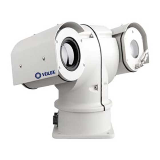
Thermal Imaging Integrated Network Camera Product Overview User Manual Figure 1-1 Appearance and interfaces of the thermal camera 1.3 Cable Connection Figure 1-2 the multi-connector combination cable of the thermal imaging integrated network camera. For details about the multi-connector combination cable, see Table 1- Figure 1-2 Multi-connector combination cable Data control line Power &... -
Page 10: Functions And Features
Thermal Imaging Integrated Network Camera Product Overview User Manual Core of Cable Functions Thin Blue A(RS485) Yellow B(RS485) Thin Grey White Black BNC output Blue NC(Reserved for Audio) Grey NC(Reserved for Audio) 1.4 Functions and Features Use uncooled infrared focal plane sensor ... -
Page 11: Device Dimensions
Thermal Imaging Integrated Network Camera Device Dimensions User Manual Device Dimensions Figure 2-1 shows the dimensions of the thermal imaging integrated network camera. Dimensions (unit: mm) Issue V1.0 (2014-01-10) -
Page 12: Installation
Thermal Imaging Integrated Network Camera Installation User Manual Installation 3.1 Preparations You may need the tools and accessories shown in Table 3-1 during the installation (you need to prepare the tools by yourself, and the accessories are in the package of the camera). -
Page 13: Installation Mode
Thermal Imaging Integrated Network Camera Installation User Manual 3.2 Installation Mode The thermal imaging integrated camera can be installed on the ceiling or the wall. You can select the appropriate installation according to your requirements. If the camera needs to be installed on the cement wall, you need to install the expansion screws (the mounting holes of the screws must be consistent with that of the support), and then install the support. - Page 14 Thermal Imaging Integrated Network Camera Installation User Manual Step 3 Fix the installation base on the wall, as shown in Figure 3-2. Figure 3-2 Fixing base Step 4 Align If using on the Vehicle-Bone, please install the Shock absorber first in the bottom of PTZ before fixing the PTZ.
-
Page 15: Quick Configuration(Thermal Module)
Thermal Imaging Integrated Network Camera Quick Configuration(Thermal module) User Manual Quick Configuration(Thermal module) 4.1 Login and Logout You must use Internet Explorer 6 or a later version to access the web management system; otherwise, some functions may be unavailable. Login system Step 1 Open the Internet Explorer, enter the IP address of IP camera (default value: 192.168.0.120) in the address box, and press Enter. -
Page 16: Main
Thermal Imaging Integrated Network Camera Quick Configuration(Thermal module) User Manual The main page is displayed. ----End logout To logout of system, click Sign out in the upper right corner of the main page, the login page is display after you log out of the system. 4.2 Main page layout On the main page, you can view real-time video, set parameter, Video parameter, Video control, PTZ control, PTZ Configure and log out of the system. -
Page 17: Browsing Video
Thermal Imaging Integrated Network Camera Quick Configuration(Thermal module) User Manual Element Description Video control You can perform the following operation in this area: area Switch between cameras. Start or stop playing Videos. Start or stop playing audio. ... - Page 18 Thermal Imaging Integrated Network Camera Quick Configuration(Thermal module) User Manual In the display dialog box, click Add, as shown in Figure 4-3. Figure 4-3 Adding the a trusted site Step 2 In the Internet Explorer, choose Tool > Internet Options > Security > Customer level, and set Download unsigned ActiveX control and initialize and script ActiveX controls not marked as safe for scripting under ActiveX controls and plug-ins to Enable, as shown in Figure 4-4.
-
Page 19: Download The Right Control In The Internet Explorer
Thermal Imaging Integrated Network Camera Quick Configuration(Thermal module) User Manual The login page is display when the control is loaded. 4.3.2 Download the right control in the Internet Explorer Preparation User uses the Internet Explorer browse video. Real-time video page pop-ups the message “clicks to play live video with ActiveX control to reduce latency”... -
Page 20: In The Google, Firefox, Or Safari Browsers Watch Real-Time Video
Thermal Imaging Integrated Network Camera Quick Configuration(Thermal module) User Manual Figure 4-6 Download control tips Click the message “click to play live video with ActiveX control to reduce latency”, jump download Adobe Flash Player Plugin control interface, once downloading is complete, you can watch video screen. - Page 21 Thermal Imaging Integrated Network Camera Quick Configuration(Thermal module) User Manual Default gateway Dynamic Host Configuration Protocol (DHCP) Preferred Domain Name System (DNS) server Alternate DNS server Procedure Step 1 Choose Device Configuration > Local Network. The Local Network page is displayed, as shown in Figure 4-7. Figure 4-7 Local Network page Step 2 Set the parameters according to Table 4-2.
- Page 22 Thermal Imaging Integrated Network Camera Quick Configuration(Thermal module) User Manual Parameter Description Setting Device obtain an The device automatically [Setting method] IP address obtains the IP address from the Click the option button. automatically DHCP server. NOTE To query the current IP address of the device, you must query it on the platform based on the...
- Page 23 Thermal Imaging Integrated Network Camera Quick Configuration(Thermal module) User Manual Step 3 Click OK. If the message "Network Parameter Updated" is displayed, click OK. The system saves the settings. The message "Set network pram’s success, Please login system again" is displayed. Use the new IP address to log in to the web management system.
-
Page 24: Parameter Setting
Thermal Imaging Integrated Network Camera Parameter Setting User Manual Parameter Setting 5.1 Sensor Configuration Interface Operation Procedure Step 1 On the Internet Explorer interface or the client software interface, select and right-click the surveillance image to the set, as shown in Figure 5-1. Figure 5-1 Sensor configuration Step 2 Choose Sensor Configuration. - Page 25 Thermal Imaging Integrated Network Camera Parameter Setting User Manual Table 5-1 lists the image setting parameters. Table 5-1 Image setting parameters Parameter Description Setting The temperatures of the temperature fields detected by the thermal imaging camera are separately mapped to values ranging from 0 to 255 by the algorithm.
-
Page 26: Fec Mode
Thermal Imaging Integrated Network Camera Parameter Setting User Manual Parameter Description Setting Off: the image is not flipped. Select from the drop-down list Horizontal: the image is flipped left and right. box. Vertical: the image is flipped up and down. [Default value] Horizontal + vertical: the image is rotated at 180 degree. - Page 27 Thermal Imaging Integrated Network Camera Parameter Setting User Manual Parameter Description Setting FFC operations can prevent the grainy and image degradation problems. The FFC is especially important when the temperature of the camera changes. For example, after the camera is powered on or the ambient temperature changed, should...
-
Page 28: Dnr
Thermal Imaging Integrated Network Camera Parameter Setting User Manual Parameter Description Setting Manual: In the manual or external FFC mode, the camera does not automatically perform the Flat Field FFC based on the temperature change or the Correction specified period. You can press the Do FFC button. -
Page 29: Lens Control
Thermal Imaging Integrated Network Camera Parameter Setting User Manual 5.5 Lens Control Figure 5-5 shows the lens control interface. Figure 5-5 Lens control interface The electrical focusing lens can be controlled and adjusted. 5.6 Temperature detection parameters Configuration instructions Temperature unit default in Celsius degrees (℃), Fahrenheit (℉) Optional Ambient temperature is for outside environment, it is changeable for user, and inside cavity temperature is not editable. -
Page 30: Temp Detection Area Configuration
Thermal Imaging Integrated Network Camera Parameter Setting User Manual Figure 5-6 Temp detection configure 5.7 Temp detection area configuration Figure 5-7 Temp area selection Issue V1.0 (2014-01-10) -
Page 31: Alarm Configuration
Thermal Imaging Integrated Network Camera Parameter Setting User Manual Figure 5-8 Temp area setting Configuration instructions Default with general mode. Preset mode optional General mode is used in constant place. Preset mode is used for PTZ thermal. Configure the not more than five regions. Hold down the left mouse button to set the frame area, right-click the mouse in a regional context can be deleted region 5.8 Alarm Configuration... - Page 32 Thermal Imaging Integrated Network Camera Parameter Setting User Manual Step 7 After the configuration is complete click the OK button Configuration instructions In the area selection full-screen mode, change the emissivity and target distance, that is, change the target emissivity and distance in all regions Alarm threshold and trends alarm can enable at same time, but the system defaults to the threshold alarm priority above trend alarm.
-
Page 33: Nvms Temperature Detection Settings
Thermal Imaging Integrated Network Camera NVMS Temperature Detection Settings User Manual NVMS Temperature Detection Settings 6.1 Configure the temperature detection parameters 6.1.1 Installation. ind the installation file in the CD, and click setup to run the installation. When installation succeed, there will be a icon NVMS in the desktop, click to open the login page. -
Page 34: Temperature Detection Paratemeters
Thermal Imaging Integrated Network Camera NVMS Temperature Detection Settings User Manual The menu of Thermal cameras will be displayed in the middle of the new page, picture shown below. When configure Thermal menu done, the NVMS will detect the temperature and display the temperature in the live window of Thermal image. -
Page 35: Detection Area
Thermal Imaging Integrated Network Camera NVMS Temperature Detection Settings User Manual Environment temperature is needed as a reference to the Thermal camera to have better correct temperature detection. Correction parameters allow you to correct the difference temperature compared with the real temp when needed. - Page 36 Thermal Imaging Integrated Network Camera NVMS Temperature Detection Settings User Manual Detection area page On the live video, the temperature of selected area will be displayed as below. Example: Issue V1.0 (2014-01-10)
-
Page 37: Alarm Configuration
Thermal Imaging Integrated Network Camera NVMS Temperature Detection Settings User Manual 6.2.3 Alarm configuration Select full screen mode or a selected area to open the alarm. You may choose the target emissivity and distance. Three type of Alarm is available: Threshold Alarm: including 2 threshold, Warning and Alarm threshold. - Page 38 Thermal Imaging Integrated Network Camera NVMS Temperature Detection Settings User Manual Alarm configuration page: Real-time alarm interface Issue V1.0 (2014-01-10)
-
Page 39: Mapping Configuration
Thermal Imaging Integrated Network Camera NVMS Temperature Detection Settings User Manual 2.2.4 Mapping configuration Used for the dual vision: Thermal+ Optical mode. To allow the temperature displayed on the normal optical window. Configuration page: Dual window Thermal PTZ: Issue V1.0 (2014-01-10) -
Page 40: Text/Picture Message Alarm(Sms/Mms)
Thermal Imaging Integrated Network Camera NVMS Temperature Detection Settings User Manual Real-time alarm interface 2.2.5 Text/Picture Message Alarm(SMS/MMS) This function is based on customer demand, specifically integrate third- party SMS / MMS alarm module can be realized: the target area exceeds the alarm threshold, send the target information includes geographic location to the user administrator. -
Page 41: Temperature Curves Query
Thermal Imaging Integrated Network Camera NVMS Temperature Detection Settings User Manual Third party device can be wireless modem or other same device, below fore reference. Wireless SMS/MMS modem 2.2.6 Temperature curves Query This function allows query the highest temperature curves of the full screen or a selected area. - Page 42 Thermal Imaging Integrated Network Camera NVMS Temperature Detection Settings User Manual When find the logs, double click to see the curve: Example full screen high temperature: Issue V1.0 (2014-01-10)
-
Page 43: Technical Specifications
Thermal Imaging Integrated Network Camera Technical Specifications User Manual Technical Specifications Table 6-1 lists the specifications of the thermal imaging integrated camera. Table 7-1 Technical specifications Description SN-TPT4230LM Sensor type Uncooled IR focal plane sensor Effective pixel 420×315 Sense method Micro bolometer Pixel distance 25um... - Page 44 Thermal Imaging Integrated Network Camera Technical Specifications User Manual Output image resolution D1/ CIF Output frame rate 30fps 1/2.8”SONY Exmor CMOS Sensor Sensor Resolution/frame rate 1920(h)x1080(v) / 25fps 0.2Lux (F1.2,AGC ON,ICR Minimum illumination >50dB WDR range 70dB Visible Day/Night Removable ICR light F= 4.7mm(F1.6) - 103 22X Optical Lens...
- Page 45 Thermal Imaging Integrated Network Camera Technical Specifications User Manual IPv4/v6、RTSP/RTP/RTCP、 network TCP/UDP、HTTP、DHCP、 features Network protocol DNS、FTP、DDNS、 PPPOE、SMTP、SIP Storage communication CIFS、 NFS protocol In-built WEB service enabling WEB management remote IE viewing and configuration Remote upgrade and Support maintenance Integration feature Onvif/third party protocol Max user login Max simultaneous 10 user login...
- Page 46 Thermal Imaging Integrated Network Camera Technical Specifications User Manual Operation temperature Temp:-20℃~+50℃ RH90% MAX(Non- Relative humidity condensing) Protection level IP66 Installation method Wall/ceiling mounting Weight 10Kg Issue V1.0 (2014-01-10)
-
Page 47: A Hazardous Substance Declaration
Thermal Imaging Integrated Network Camera Hazardous Substance Declaration User Manual Hazardous Substance Declaration Hazardous Substance or Element Hexavalent Polybrominated Component Plumbum Mercury Cadmium Polybrominated Chromium Diphenyl Ethers (Pb) (Hg) (Cd) Biphenyls (PBB) (Cr6+) (PBDE) Structural ○ ○ ○ ○ ○ ×... - Page 48 Veilux Inc 802 Greenview Dr. Suite 200, Grand Prairie TX. 75050 USA Toll Free: 1-800-510-6528 Dir ect: (+1) 214 635-4855 Fax: (+1) 214 988-2858 www.veilux.net sales@veilux.net www.veilux.net...
Need help?
Do you have a question about the VPIP-THERMAL-XX22 and is the answer not in the manual?
Questions and answers