
Related Manuals for SCHUNK ELKE 24/2F


Summary of Contents for SCHUNK ELKE 24/2F
- Page 1 Electrical Control Unit Type ELKE 24/2F with RSS Assembly and Operating Manual 02/ELKE/en/2010-04-12/SW Document last updated: 2010-04-12...
- Page 2 Dear Customer, Congratulations on choosing a SCHUNK product. By choosing SCHUNK, you have opted for the highest precision, top quality and best service. You are going to increase the process reliability of your production and achieve best machining results – to the customer's complete satisfaction.
-
Page 3: Table Of Contents
Table of contents Table of contents About this manual ....................5 Purpose/validity ..................5 Target groups ..................... 5 Applicable documents ................5 Symbols in this manual ................6 Basic safety notes ....................7 Intended use ....................7 Environmental and operating conditions ............ 7 Controlled production ................. - Page 4 Table of contents End of the clamping or opening procedure is not correctly detected ..39 End of the clamping procedure is detected too early ....... 40 End of the clamping procedure is detected too late or not at all ....40 End of the opening procedure is detected too early .........
-
Page 5: About This Manual
About this manual About this manual Purpose/validity This manual is part of the module and describes the safe and proper use during all phases of operation. This manual is valid only for the module specified on the front page. Target groups Target group Task ... -
Page 6: Symbols In This Manual
About this manual Symbols in this manual To give you quick access to information, the following symbols will be used in this guide: Symbol Meaning Dangers for persons. WARNING Nonobservance can cause death or serious injuries. NOTICE Information on avoiding material damage. ... -
Page 7: Basic Safety Notes
Basic safety notes Basic safety notes Intended use The (ELKE 24-2F) electrical control unit is not a safety component. The electrical control unit is used to control max. two pneumatic chucks for lathes. The module is intended for installation in a machine. The requirements of the applicable guidelines must be observed and complied with. -
Page 8: Controlled Production
2.3.1 Constructional changes, attachments, or modifications Additional drill holes, threads, or attachments that are not offered as accessories by SCHUNK may be attached only with permission of SCHUNK. Personal qualification The assembly, initial commissioning, maintenance, and repair of the module may be performed only by trained specialist personnel. -
Page 9: Warranty
Also observe our general terms of business. Scope of delivery The scope of delivery includes: • Electrical Control Unit ELKE 24/2F with RSS The following accessories are required for the module: • Connection cable with Harting plug in the version ordered: –... -
Page 10: Technical Data
Technical Data Technical Data Further technical data can be found in our catalog. The most recent version applies. Type ELKE 24/2F with RSS weight [kg] dimension see chapter 12 page 46 power supply [V DC] 24 (stabilized) ±10% Current input during idle running [mA] 2.30... -
Page 11: Description Of The Unit
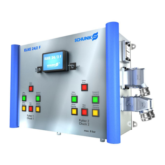
Description of the unit Description of the unit Configuration /13/ /12/ /11/ /10/ Key switch for "Teach in" function Button for controlling chuck 2 Bicolor display Pilot lamps for chuck 2 (1x red, 2x green) Key switch for all five operating modes /10/ Connections for the foot switch Pilot lamps for chuck 1 (1x red, 2x green) -
Page 12: Function
Description of the unit Function ELKE 24/2F is an electrical control unit for controlling pneumatic chucks for lathes. The control unit can be used for all chuck sizes. A maximum of two chucks can be controlled. There are five possible operating modes: •... -
Page 13: Assembly
Assembly Assembly Mechanical connection WARNING Risk of injury when the machine/system moves unexpectedly! Switch off power supply. Figure 2 Install the module onto the lathe using the four fixing Mounting brackets. The customer must provide the following mounting material: •... -
Page 14: Electrical Connection
Assembly Electrical connection WARNING Risk of injury when the machine/system moves unexpectedly! Switch off power supply. Note • Observe the requirements for the power supply (see chapter 5, page 10). Observe the pin assignment. /12/ /11/ /10/-1 /10/-2 /10/-1 Connections for foot switch 1 /11/... - Page 15 Assembly Pin allocation for the simple Harting plug connectors ® (Han-Modular Compact) Allocation +24 V +24 V "Foot switch connected" signal "Foot switch stop / open" signal "Foot switch stop / closed" signal Table 1 Allocation terminal block A for the foot switch Pin allocation for the double Harting plug connectors ®...
-
Page 16: Air Connection
Assembly Air connection WARNING Risk of injury when the machine/system moves unexpectedly! Switch off power supply. Note • Observe the requirements for the air supply (see chapter 5, page 10). Use separate compressed air lines for each chuck. Figure 4 Air connection chuck 1 and chuck 2 Item Designation Function... -
Page 17: Assembly Example
Figure 5 Item Designation Chuck 1 Chuck 2 ELKE 24/2F electrical control unit Feed line with pressure control for chuck 1 Feed line with pressure control for chuck 2 Foot switch for chuck 1 Foot switch for chuck 2 Connection to machine control system 24 V... -
Page 18: Commissioning And Operation
Commissioning and operation Commissioning and operation Overview of operation Power up Power-up messages Version & Date Foot switch mode RSS mode Right key switch "Teach In" Select operating mode Left key switch Teach-in mode part 1: prepare messages Open chuck Execute operating mode Open chuck Buttons: "stop"... -
Page 19: Power-Up Messages
Commissioning and operation Power-up messages Power-up messages are shown on the LCD display of the ELKE 24/2F when the power supply is switched on. Power-up message 1 displays information on the firmware for three seconds: • Version number (release) •... - Page 20 Commissioning and operation In the "stay" mode, the operator has to remain stood on the foot switch for as long as it takes for the ELKE 24/2F to recognize the end of the movement. In the "tap" mode, the operator only has to actuate the foot switch once to release the movement.
-
Page 21: Selecting The Operating Mode
Emergency stop = H or start teach-in process. (active low) Operating hours: 3.0 h Spindle has stopped Figure 11 General readiness for operation display The ELKE 24/2F is ready to select the operating mode or to teach in (again). 02/ELKE/en/2010-04-12/SW... - Page 22 Figure 12 Spindle turns display The ELKE 24/2F is disabled and does not react to any key inputs until the "Spindle has stopped" signal from the PLC is set to High again. In this status, the internal states of ELKE 24/2F (chuck tightened/open) and the output signals to the PLC are retained.
- Page 23 Commissioning and operation There is no error on the PLC inputs ("Emergency stop" Selecting the operating mode and "Spindle has stopped"). Select an operating mode: Turn the left key switch into one of the three positions: a) Neutral position (key vertical) The current operating mode is retained here.
- Page 24 Commissioning and operation Synchronous clamping Name of Status of Select movement operating supply P: 5.8 bar P: 5.7 bar mode pressures Figure 14 "Synchronous clamping" operating mode is set The "Select movement" text is initially displayed in the second line. Displayed in the third line is the respective current air pressure in supply line P in the selected unit of pressure (bar or psi).
- Page 25 Commissioning and operation After the clamping or opening procedure has finished, the reading for the working pressure is, however, maintained permanently until the next procedure and is not updated further. This allows the previously reached clamping or opening pressure to be controlled. (The actual pressure in the control line drops to 0 bar after the procedure has ended).
- Page 26 The RSS system is comprised of the following components: RSS R1 receiver in the ELKE 24/2F RSS W1 or RSS P1 transmitter in the chuck, with a path sensor (for RSS W1) or a pressure sensor...
- Page 27 CAUTION: The RSS mode is NOT for clamping and DANGER processing workpieces. Since in this mode the pressure is not monitored and the chuck jaws can only be moved manually, ELKE 24/2F cannot define the end of the clamping procedure here. 02/ELKE/en/2010-04-12/SW...
-
Page 28: Teach-In Mode
Teach-in mode To be able to automatically recognize the end of a chuck's clamping or opening procedure, the ELKE 24/2F initially has to be taught into the connected chuck. In the process, the pressure sequences are measured and suitable parameters are determined. - Page 29 Commissioning and operation 2. Keep the left and right "open" buttons pressed down together or one after the other until the jaws of both chucks have opened out completely. Important: The buttons have to stay pressed down by hand for as long as it takes to open out the jaws completely.
- Page 30 Commissioning and operation Teach-in mode: Chuck 1 Sup. P: 4.6 bar (4.7) Lne A: 0.0 bar (4.4) Lne B: 0.0 bar (4.4) Figure 21 Starting the measurement The value in brackets shows the last taught-in reference pressure/pressure of the respective line. Line Designation Unit...
- Page 31 Commissioning and operation the new pressure to be reached for the clamping procedure and buffered. Teach-in mode: Chuck 1 Sup. : 5.91 bar (5.91) Lne A: 5.71 bar (5.73) Lne B: 0.00 bar (5.70) Figure 22 Teaching in the clamping procedure The pressure sequences must now also be measured for Carrying out the the closing together process.
- Page 32 Commissioning and operation After the measurements are finished, the new taught-in values for P, A and B are displayed in brackets for three seconds in the LCD display in the last column. Carrying out the Chuck 2 is taught in analogously to chuck 1: measurement for ...
- Page 33 Commissioning and operation The LCD display shows the button assignment for Changing the parameters changing parameters manually: manually: Change parameter C1 <(back) (exit) (forw.) (-) (save) (+)> P supply: 5.91 bar Figure 25 Display for changing parameters Line Designation Displays for which chuck the parameters are being readjusted.
- Page 34 Commissioning and operation The following parameters can be set separately for chuck 1 or chuck 2: Parameter Description P supply Reference pressure for the chuck's supply line in bar or psi P clamped Required clamping pressure for the chuck in bar or psi. (In operating mode "Separate I.D.
- Page 35 Commissioning and operation Parameter Description opening pressure deviates by less than the value stored here in % from the taught-in opening pressure for P open. (In operating mode "Separate I.D. clamping", this deviation is used as the deviation permitted for I.D. clamping). +t clamped Additional time in milliseconds in which the clamping line is still pressurized with compressed air after the clamped conditions have...
- Page 36 Commissioning and operation General parameters can also be displayed or set: Parameter Description Unit of pressure Either "bar" or "psi" can be selected for the display of the unit of pressure. Internally, all pressures are processed in millibars, which means that there could be roundoff errors if the display is shown in psi.
- Page 37 Commissioning and operation /10/ dP gespannt = P1-A1 -500 1000 1500 2000 2500 3000 Zeit [ms] Figure 26 Significance of the chuck-specific configuration parameters illustrated with the support of pressure sequences during clamping Item Designation Point in time of "start": A clamping procedure is initiated by pressing the Clamp button Point in time of "clamping pressure reached": The pressure differential of supply line P and the control line (here A) falls below the taught-in threshold...
- Page 38 Commissioning and operation Item Designation "±% clamped" parameter: The permitted range of the clamping pressure /10/ "+t clamped" parameter: Additional clamping time Table 9 Legend for Figure 26 For an opening procedure (without figure), the afore- mentioned applies with the following counterparts: Parameter name for Parameter name for "clamping"...
-
Page 39: Troubleshooting
Troubleshooting Troubleshooting Electric signals are not transmitted Possible cause Corrective action Check the supply lines for defects; exchange if needed. Interruption in the supply lines Check the electrical connections (see chapter 7.2, page 14) Table 11 Possible causes of error and appropriate measures to be taken Compressed air is not conveyed Possible cause Remedial measures... -
Page 40: End Of The Clamping Procedure Is Detected Too Early
Troubleshooting If the end of a clamping or opening procedure cannot be detected despite teaching in again, then the relevant parameters can be adapted manually if necessary. The tables in the following subsections describe appropriate measures to be taken. End of the clamping procedure is detected too early Possible cause Remedial measures... -
Page 41: End Of The Opening Procedure Is Detected Too Early
Troubleshooting End of the opening procedure is detected too early Possible cause Remedial measures The supply pressure deviates strongly Teach in the parameters again from the supply pressure during teach The device already reacts to a too Reduce "dP open" parameter great a pressure differential for "dP open"... -
Page 42: Error Messages
Troubleshooting Error messages The device detects various errors independently and shows these in the second line of the LCD display as follows: Message Meaning Remedial measures Check the chuck (distributor The clamping or opening procedure exceeds the set time ring) and control line for leakage Timeout! ... - Page 43 Troubleshooting Message Meaning Remedial measures Compressed air supply P is outside the permissible range: During a clamping or opening procedure, the Check the supply lines for pressure for compressed air defects; exchange if needed. supply P must be greater ...
-
Page 44: Maintenance And Care
Maintenance and care Maintenance and care 10.1 Maintenance intervals We recommend that you have SCHUNK carry out all repair work. Maintenance Type ELKE 24/2F with RSS intervals Visual Regularly along with machine or system inspection maintenance Cleaning As required Tab. 19... -
Page 45: Transport, Storage And Disposal
Observe the maximum stacking height of two packaged modules. 11.4 Disposal Observe the locally valid legal disposal regulations. Environmentally sound disposal via the corresponding recycling or workshop centers. Schunk GmbH & Co. KG accepts no liability for the consequences of incorrect disposal. 02/ELKE/en/2010-04-12/SW... -
Page 46: Assembly Drawing
Assembly drawing Assembly drawing Figure 27 dimension of ELKE 24/2F with RSS 02/ELKE/en/2010-04-12/SW... -
Page 47: Contact
Contact Contact GERMANY – HEAD OFFICE CANADA DENMARK HUNGARY SCHUNK GmbH & Co. KG SCHUNK Intec Corp. SCHUNK Intec A/S SCHUNK Intec Kft. Spann- und Greiftechnik 190 Britannia Road East, Storhaven 7 Széchenyi út. 70. Bahnhofstrasse 106 – 134 Units 23-24... - Page 48 Fax +82-31-7376142 info@kr.schunk.com www.kr.schunk.com MEXICO, VENEZUELA PORTUGAL SPAIN TURKEY SCHUNK Intec S.A. de C.V. Sales Representative SCHUNK Intec S.L. SCHUNK Intec Bağlama Sistemleri ve Av. Luis Vega y Monroy # 332 Victor Marques Foneria, 27 Otomasyon San. ve Tic. Ltd. Şti.
Need help?
Do you have a question about the ELKE 24/2F and is the answer not in the manual?
Questions and answers