Table of Contents
Advertisement
Quick Links
Tooling needed to properly perform this repair.
1) Lube Nozzle for E-Attachments (00001A)
2) Threaded Ring Removal Tool (10112D)
3) Mini Phillips Head Screwdriver
4) Mini Flat Head Screwdriver
5) Adjustable Wrench
6) Mini Channel Lock Pliers
Step 2:
Using an adjustable wrench (as pictured), unscrew the back cap. Again, it is regular thread so turn the
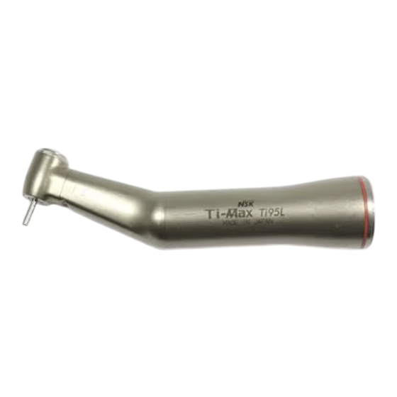
NSK Ti-Max Ti95L
Repair Procedure
Step 1:
Remove the small Phillips Head screw on the neck assembly using your
mini Phillips Head screwdriver. It is regular thread, so turn the screw
counterclockwise to loosen.
cap counterclockwise to loosen. WARNING: Do Not Use any type of
Channel Lock pliers on the back cap, they may damage the cap.
Advertisement
Table of Contents

Related Manuals for NSK Ti-Max Ti95L


Summary of Contents for NSK Ti-Max Ti95L
- Page 1 NSK Ti-Max Ti95L Repair Procedure Tooling needed to properly perform this repair. 1) Lube Nozzle for E-Attachments (00001A) 2) Threaded Ring Removal Tool (10112D) 3) Mini Phillips Head Screwdriver 4) Mini Flat Head Screwdriver 5) Adjustable Wrench 6) Mini Channel Lock Pliers...
- Page 2 Step 3: Now, pull the head assembly straight out of the neck of the attachment. WARNING: Do Not twist the head assembly as you pull it out as this may result in damage to the water lines and fiber optics. Now locate the upper water line o- rings.
- Page 3 Part # Description 90132 Back Cap 90133 Turbine Cartridge Head Shell 90126 – Modified Drive Shaft Screw 90139 Drive Shaft 90126 Neck Screw Main Body Part # Description Main Body 90139T Tail Assembly 90139M Lower Manifold...
- Page 4 Remove the screw heads using a mini Flat Head screwdriver. Then remove the cylinder shaped o-rings (part# 90148). You should now have a disassembled NSK TiMax Ti95L Attachment Clean all component parts thoroughly. It is safe to place them in your ultra-sonic cleaner.
- Page 5 Step 12: Now insert a new turbine cartridge (part# 90133) into the head assembly. Please place the turbine properly into the head using the small alignment nub on the cartridge and pushing it into the obvious groove on the inside of the head shell. After inserting the cartridge fully, screw the back cap onto the head shell.
- Page 6 Step 15: Now insert the head assembly into the neck of the attachment. Again, do not twist the assembly while inserting it as this may cause damage to the waterlines or fiber optics. If the head does not sit flush on the neck of the attachment, twist the bur slightly while applying minor downward pressure to align the internal gearing.
Need help?
Do you have a question about the Ti-Max Ti95L and is the answer not in the manual?
Questions and answers