Table of Contents
Advertisement
Quick Links
20220119
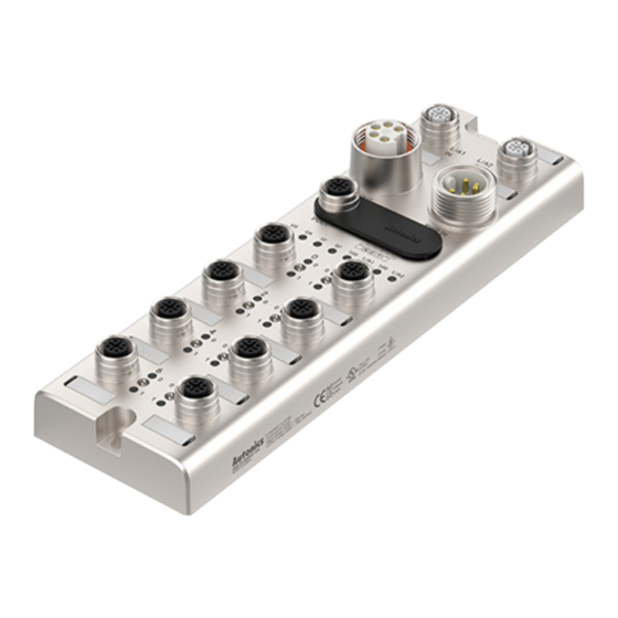
Remote I/O Boxes
(PROFINET)
ADIO-PN
PRODUCT MANUAL
For your safety, read and follow the considerations written in the instruction
manual, other manuals and Autonics website.
The specifications, dimensions, etc. are subject to change without notice for product
improvement. Some models may be discontinued without notice.
Features
• The upper level communication protocol: PROFINET
• The lower level communication protocol: IO-Link ver. 1.1 (port class: Class A)
• Housing material: Zinc Die casting
• Protection rating: IP67
• The daisy chain allows the power supply using the connection technology
in a standardized 7/8" connector
• The maximum output current of power supply: 2 A per port
• I/O port settings and status monitoring
(cable short / disconnection, connection status, etc.)
• Supports digital input filter
ᜢ ᜨ ᜣ ᜬ
Safety Considerations
• Observe all 'Safety Considerations' for safe and proper operation to avoid hazards.
• symbol indicates caution due to special circumstances in which hazards may occur.
Warning
Failure to follow instructions may result in serious injury or death.
01. Fail-safe device must be installed when using the unit with machinery
that may cause serious injury or substantial economic loss.(e.g. nuclear
power control, medical equipment, ships, vehicles, railways, aircraft,
combustion apparatus, safety equipment, crime/disaster prevention
devices, etc.)
Failure to follow this instruction may result in personal injury, economic loss or
fire.
02. Do not use the unit in the place where flammable/explosive/corrosive gas,
high humidity, direct sunlight, radiant heat, vibration, impact or salinity
may be present.
Failure to follow this instruction may result in explosion or fire.
03. Do not connect, repair, or inspect the unit while connected to a power
source.
Failure to follow this instruction may result in fire.
04. Check 'Connections' before wiring.
Failure to follow this instruction may result in fire.
05. Do not disassemble or modify the unit.
Failure to follow this instruction may result in fire.
06. Do not touch the product during operation or for a certain period of time
after stopping.
Failure to follow this instruction may result in burn.
Caution
Failure to follow instructions may result in injury or product damage.
01. Use the unit within the rated specifications.
Failure to follow this instruction may result in fire or shortening the life cycle of the
product.
02. Use a dry cloth to clean the unit, and do not use water or organic solvent.
Failure to follow this instruction may result in fire.
03. Keep the product away from metal chip, dust, and wire residue which flow
into the unit.
Failure to follow this instruction may result in fire or product damage.
04. Connect the cable correctly and prevent poor contact.
Failure to follow this instruction may result in fire or product damage.
05. Do not connect or cut off the wire of the cable while operating the unit.
Failure to follow this instruction may result in fire or product damage.
Cautions during Use
• Follow instructions in 'Cautions during Use' . Otherwise, it may cause unexpected
accidents.
• The UA power (actuator power) and US power (sensor power) should be insulated by
the individually isolated power device.
• Power supply should be insulated and limited voltage/current or Class 2, SELV power
supply device.
• Use the rated standard cables and connectors. Do not apply excessive power when
connecting or disconnecting the connectors of the product.
• Keep away from high voltage lines or power lines to prevent inductive noise.
In case installing power line and input signal line closely, use line filter or varistor at
power line and shielded wire at input signal line.
For stable operation, use shield wire and ferrite core, when wiring communication wire,
power wire, or signal wire.
• Do not use near the equipment which generates strong magnetic force or high
frequency noise.
• Do not connect, or remove this unit while connected to a power source.
• This unit may be used in the following environments.
- Indoors (in the environment condition rated in 'Specifications')
- Altitude max. 2,000 m
- Pollution degree 2
- Installation category II
Advertisement
Table of Contents

Related Manuals for Autonics ADIO-PN


Summary of Contents for Autonics ADIO-PN
- Page 1 For stable operation, use shield wire and ferrite core, when wiring communication wire, manual, other manuals and Autonics website. power wire, or signal wire. The specifications, dimensions, etc. are subject to change without notice for product •...
- Page 2 The figure below shows the PROFINET network and the devices that compose it. For proper use of the product, refer to the manuals and be sure to follow the safety considerations in the manuals. Download the manuals from the Autonics website. Project planning software + GSDML file...
-
Page 3: Ordering Information
Function Software Not Connected (N.C.) Data - Download the installation file and the manuals from the Autonics website. ■ atIOLink atIOLink with purposes for setting, diagnosis, initialization and maintenance of IO-Link Not Connected (N.C.) device via IODD file is provided as the dedicated Port and Device Configuration Tool Data + (PDCT). - Page 4 -|Transparent Guide|- Dimensions • Unit: mm, For the detailed dimensions of the product, follow the Autonics website. 33.4 Ø4.5 M4 X 0.7 8.35 Ø4.5 29.6...
-
Page 5: Unit Descriptions
-|Transparent Guide|- Unit Descriptions Installation ■ Mounting 01. Prepare a flat or metal panel in the enclosure. 02. Drill a hole to mount and ground the product on the surface. 03. Turn off all power. 04. Fix the product using M4 screws in the mounting holes. Tightening torque: 1.5 N m ■... -
Page 6: Device Name Settings
04. The device name has been changed. 05. Put the protective cover on the rotary switches. ■ atIOLink The PROFINET device name configured by the atIOLink software is stored in the ADIO-PN's EEPROM. For more information, refer to the atIOLink User Manual. -
Page 7: Port Connections
-|Transparent Guide|- Port Connections ■ Port specifications • Be sure to check the port specifications below before connecting the device. Prepare a cable that complies with the protection rating IP67. Ethernet port I/O port PDCT port Power supply port M12 (Socket-Female), 4-pin, M12 (Socket-Female), 5-pin, M12 (Socket-Female), 5-pin, Input: 7/8”... - Page 8 -|Transparent Guide|- Port Connections 03. Connect with the atIOLink Do not use the PDCT port and the Ethernet port at the same time. 01. Connect the M12 connector to the PDCT port. See the connections below. Not Connected (N.C.) Data - Not Connected (N.C.) Data +...
- Page 9 -|Transparent Guide|- Indicators ■ Status indicator ■ I/O port indicator 01. The power supply of sensor 01. Pin 4 (C/Q) Indicator LED color Status Description Indicator LED color Status Description Applied voltage: normal DI/DO: pin 4 OFF Yellow Green Flashing The settings of the rotary switches is DI/DO: pin 4 ON (1 Hz)
-
Page 10: Specifications
W 66 × H 215 × D 38 mm Address settings Rotary switches, DCP, atIOLink Material Zinc Die casting GSDML file Download the GSDML file at the Autonics website. M12 (Socket-Female), 4-pin, D-coded, Push-Pull Ethernet port Number of ports: 2 (IN/OUT) ■ IO-Link Supported function: daisy chain Input: 7/8”...
Need help?
Do you have a question about the ADIO-PN and is the answer not in the manual?
Questions and answers