Table of Contents
Advertisement
Quick Links
Advertisement
Table of Contents

Related Manuals for Autonics ARD Series


Summary of Contents for Autonics ARD Series
- Page 1 USER MANUAL © Copyright Reserved Autonics Co., Ltd.
- Page 2 © Copyright Reserved Autonics Co., Ltd.
-
Page 3: Preface
Preface Preface Thank you for purchasing Autonics product. Please familiarize yourself with the information contained in the Safety Precautions section before using this product. This user manual contains information about the product and its proper use, and should be kept in a place where it will be easy to access. -
Page 4: User Manual Guide
Visit our web site (www.autonics.com) to download a copy. The manual's content may vary depending on changes to the product's software and other unforeseen developments within Autonics, and is subject to change without prior notice. Upgrade notice is provided through out homepage. ... -
Page 5: User Manual Symbols
Failure to follow instructions can result in serious injury or death. Failure to follow instructions can lead to a minor injury or product damage. An example of the concerned feature's use. Annotation mark. ※1 © Copyright Reserved Autonics Co., Ltd. -
Page 6: Safety Precautions
It may cause electric shock, human injury and breakdown of the product. Please separate as industrial waste when disusing this unit. The specifications and dimensions of this manual are subject to change without any notice. © Copyright Reserved Autonics Co., Ltd. -
Page 7: Table Of Contents
How to use IOLinx for DeviceNet ..............61 7.4.1 Position of IOLinx for DeviceNet ..............61 Running IOLinx for DeviceNet ................61 Unit parameter setting ................68 Initial screen ....................... 68 Unit information ....................69 © Copyright Reserved Autonics Co., Ltd. -
Page 8: Table Of Contents
Table of Contents 8.2.1 General tab ....................69 8.2.2 Parameter tab ..................... 70 8.2.3 I/O Data tab ....................71 8.2.4 EDS File tab ....................71 Common parameters setting for analog i/o unit ..........72 8.3.1 Generic Status .................... 73 8.3.2 Network Power Voltage ................ - Page 9 1 Product overview © Copyright Reserved Autonics Co., Ltd.
-
Page 10: Product Overview
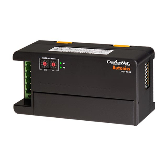
1 Product overview Product overview Features Adopts DeviceNet, standard open Network : Communiates other DeviceNet devices without additional installations : Configurable power and communication system only with communication cables : Connectable max. 63 units per 1 master unit Strong against noise and high accuracy(0.3%) measurement with differential input method(measuring difference between +, - input signal) ... -
Page 11: Part Descriptions
OFF: -10-10VDC ● ● ● Setting) Software DC4-20mA ● ● ● ● Setting Not supported DC0-20mA ● ● ● ● ● ⑥ I/O Terminal block It is terminal block for connecting external device I/O. © Copyright Reserved Autonics Co., Ltd. - Page 12 1 Product overview ※1. Status of MS LED, NS LED Type Descriptions Troubleshooting status color Green Normal operation I/O communication or message communication is working. Green Standby of duplicated address Green The status of standby for receving message of duplicated address check from master unit.
- Page 13 1 Product overview © Copyright Reserved Autonics Co., Ltd.
-
Page 14: Specifications
2 Specifications Specifications Model ARD-AI04 ARD-AO04 Power supply Rated voltage: 24VDC, Voltage range: 12-28VDC Power consumption Max. 3W Insulation type Photocoupler isolated Input 4-point Output 4-point I/O points (switchable voltage/current) (voltage 2CH, current 2CH) 0-10VDC, -10-10VDC, 0-5VDC, 0-10VDC, -10-10vDC, 0-5VDC, 1-5VDC, -5-5VDC 1-5VDC, -5-5VDC Voltage... - Page 15 Display scale ● Adjustment gradient ● I/O comment ● Offset correction ● Analog Input digital filter ● Peak/Bottom Hold ● Disconnected cable detection ● Input comparision ● Hysteresis ● Output setting for error ● © Copyright Reserved Autonics Co., Ltd.
-
Page 16: Dimensions
3 Dimensions Dimensions (unit: mm) Panel cut-out © Copyright Reserved Konics Co., Ltd. - Page 17 3 Dimensions © Copyright Reserved Autonics Co., Ltd.
-
Page 18: Connections
4 Connections Connections (1) Connections 0-5VDC DC0-20mA Curr 1-5VDC DC4-20mA Voltage -5-5VDC 0-10VDC -10-10VDC ARD-AI04 ARD-AO04 ※1. For current input, short between V and I □ + □+ (2) I/O circuit DeviceNet Type Inner circuit External connections connector Input ※1 Output... - Page 19 (3) I/O range No I/O range Max. allowable I/O range 0-5VDC -0.25-5.25VDC 1-5VDC 0.8-5.2VDC 0-10VDC -0.5-10.5VDC -5-5VDC -5.5-5.5VDC -10-10VDC -11-11VDC DC4-20mA DC3.2-20.8mA DC0-20mA DC0-21mA ※ 1 ※1: For current input, max. allowable input range is DC-1-21mA. © Copyright Reserved Autonics Co., Ltd.
-
Page 20: I/O Data Of Devicenet Analog Unit
5 I/O data of DeviceNet analog unit I/O data of DeviceNet analog unit DeviceNet analog unit is devided as input model(ARD-AI04) and output model(ARD-AO04). Each unit supports 7EA input/output range. Standard I/O range of voltage and current is same. The below descriptions are based on Defualt Scaling of Scaling at Function Choice. Voltage range of analog I/O unit (1) Voltage I/O range: DC 0 to 10 V For 0 to 10V of voltage range, analog data has the value of 0x0000 to 0x3E80 (0 to 16000). - Page 21 Max. input/output range is -5.5 to 5.5V and that of analog data is able to convert as 0xE3E0 to 0x2260(-8800 to 8800). Voltage 5.5V E3E0 E0C0 0000(0) Conversion (-8800) (-8000) Data 1F40 2260 7FFF (8000) (8800) -5.5V © Copyright Reserved Autonics Co., Ltd.
-
Page 22: Current Range Of Analog I/O Unit
5 I/O data of DeviceNet analog unit Current range of analog I/O unit (1) Current input range: DC 4 to 20 mA For 4 to 20mA of current range, analog data has the value of 0x0000 to 0x3E80(0 to 16,000). Max. - Page 23 In case that analog data is 0x0000 to 0x3E80(0 to 16,000), current range is 0 to 20mA. Max. output range is 0mA to 21mA and that of analog data is able to convert as 0x0000 to 0x41A0(0 to 16,800). © Copyright Reserved Autonics Co., Ltd.
-
Page 24: Installation And Network Wiring
6 Installation and network wiring Installation and network wiring Setup (1) Node address setup 1st Two rotary switches are used for setting node address. X10 switch represents the 10’s multiplier and X10 switch represents the 1’s multiplier. Node addresses are available from 00 to 63. (Node address should not be duplicated.) 2nd Node address is changed when supplying the power to the unit. - Page 25 There are two methods to register, regist automatically in on-line or manually in off- line. (refer to the manual of the master unit.) ARD Series I/O assignment: Usually it is automatically assigned by the software. Setting of operation mode: Select among Poll, COS, Cyclic, Bit Strobe (it is usually...
-
Page 26: Network Wiring
6 Installation and network wiring Network wiring This network consists of below items. DeviceNet cable (arterial and feeder) DeviceNet power Terminating resistances Tap (selectable) Grounding Thick line: arterial, Thin line: feeder NODE The point of connection the DeviceNet master and a slave device. Arterial At this cable, terminating resistances are installed at both ends. - Page 27 It is convenience to use taps for wiring network between ARD units at several places. Multi-drop wiring Wiring using Taps (5) Connector wiring Wiring using a tap: Connect two connectors at a tap. Multi-drop wiring: Connect two cables to one connector (accessory) © Copyright Reserved Autonics Co., Ltd.
- Page 28 6 Installation and network wiring (6) Grounding Groudning blocks external noise. If grounding is not proper, it may cause communication problem by noise. Connect Shield cable to grouding terminal (F.G.) of power supply. The cable length between power supply devicena and power tap should be below 3m. Grounding only for 1-point of power output terminal not to organizing ground loop ...
- Page 29 6 Installation and network wiring © Copyright Reserved Autonics Co., Ltd.
-
Page 30: How To Use Devicenet Configuration Tools
1st Select Start >Rockwell Software>RSLinx>Tools>EDS Hardware Installation Tool and run EDS Hardware Installation Tool. 2nd Click ‘Add’ to add the EDS of ARD-AI04, DeviceNet analog input unit of Autonics. Visit our website (www.autonics.com) to download this EDS file. © Copyright Reserved Konics Co., Ltd. - Page 31 ‘Register a single file’ registers one EDS file. ‘Register a directory of EDS’ registers several EDS files. ‘Register a directory of EDS files’ registers several EDS files of one directory. 4th ‘Select an EDS file’ dialog box appears. Select an EDS file of ARD and click ‘Next’. © Copyright Reserved Autonics Co., Ltd.
- Page 32 7 How to use DeviceNet Configuration Tools 5th You can check the path of an EDS at ‘Named:’. Click ‘Next’. 6th When EDS file testing is complete successfully, the below dialog appears. Click ‘Next’. © Copyright Reserved Konics Co., Ltd.
- Page 33 7 How to use DeviceNet Configuration Tools In case of an abnormal EDS file, the error dialog appears. Visit our website (www.autonics.com) or ODVA organization homepage (www.odva.org) to download a normal EDS file. Try it again. 7th Change the icon of added EDS.
- Page 34 7 How to use DeviceNet Configuration Tools 8th ‘Change Icon’ dialog box opens. There are several basic icons. You can use the downloaded icons. Visit our website (www.autonics.com) and download it. Click ‘Browse’ to apply the downloaded ARD icon. Select the downloaded icons of ARD.
- Page 35 7 How to use DeviceNet Configuration Tools 9th To complete installtion of EDS successfully, the below dialog as a review appears. Click ‘Next’. 10th When installation of EDS is complete successfully, the below dialog box appears. Click ‘Finish’. © Copyright Reserved Autonics Co., Ltd.
-
Page 36: Rslinx Run
7 How to use DeviceNet Configuration Tools 7.1.2 RSLinx run 1st Select Start>Rockwell Software>RSLinx Classic and run RSLinx Classic. 2nd Select Communications > RSWho of menu to create RSWho which consists of DeviceNet network by RSLinx. 3rd Select Communications > Configure Drives to configure the driver of master for recognization of DeviceNet master by RSLinx. - Page 37 4th ‘Configure Drivers’ dialog box appears. Select ‘DeviceNet Drivers (1784- PCD/PCIDS,1770-KFD,SDNPT drivers)’ of Available Driver Types. 5th Click ‘Add New’ to add it at ‘Configured Drivers’. 6th ‘DeviceNet Drivers Selection – RSLinx DeviceNet-3’ dialog box appears. Select ‘Allen-Bradley 1784-PCIDS’ and click ‘Select’. © Copyright Reserved Autonics Co., Ltd.
- Page 38 7 How to use DeviceNet Configuration Tools 7th ‘Driver Configuration’ dialog box appears to set communication of DeviceNet master. Check the Node Address of ‘DeviceNet Port Setup’ is 0 and set the proper communicaton distance by Network Baud Rate. When communication distance is within 500m, network baud rate is 125Kbps, within 250m, it is 250Kbps, and within 100m, it is 500Kbps.
- Page 39 7 How to use DeviceNet Configuration Tools 9th You can check the added driver at ‘Configure Drivers’. Click ‘Configure’ and click ‘Close’.. 10th You can check the DeviceNet master unit is added at Workspace of RSWho. © Copyright Reserved Autonics Co., Ltd.
- Page 40 7 How to use DeviceNet Configuration Tools 11th RXLinx searches network periodically and cofigure the connected slaces at master. © Copyright Reserved Konics Co., Ltd.
-
Page 41: How To Use Rsnetworx For Devicenet
How to use RSNetWorx for DeviceNet 7.2.1 EDS file register 1st Select Start>Rockwell Software>RSNetWorx>RSNetWorx for DeviceNet and run RSNetWorx for DeviceNet. 2nd Select Tools > EDS Wizard of menu to register an EDS file. © Copyright Reserved Autonics Co., Ltd. - Page 42 7 How to use DeviceNet Configuration Tools 3rd Rockwell Automation’s EDS Wizard starts and click ‘Next’.. 4th Select ‘Register an EDS file(s)’ to register an EDS file and click ‘Next’. To unregister an existing EDS, select ‘Unregister a device’. To create an EDS file, select ‘Create an EDS file’.
-
Page 43: Eds Installation Check
7 How to use DeviceNet Configuration Tools 7.2.2 EDS installation check When an EDS is registered normally by EDS Wizard, you can check Vendor > Autonics Corporation is added. © Copyright Reserved Autonics Co., Ltd. -
Page 44: Network Connection Of Rsnetworx For Devicenet
7 How to use DeviceNet Configuration Tools 7.2.3 Network connection of RSNetWorx for DeviceNet 1st Select Start>Rockwell Software>RSNetWorx>RSNetWorx for DeviceNet and run RSNetWorx for DeviceNet. 2nd Select File > New of menu to create a new Configuration View. © Copyright Reserved Konics Co., Ltd. - Page 45 7 How to use DeviceNet Configuration Tools 3rd To recognize the slave at DeviceNet master, select Network > Online to browse DeviceNet network. © Copyright Reserved Autonics Co., Ltd.
- Page 46 7 How to use DeviceNet Configuration Tools 4th ‘Browe for network’ dialog box appears. Select ‘1784-PCIDS-1, DeviceNet’ as DeviceNet master and click ‘OK’ 5th If the similar configuration exists, the dialog box as below appears. Click ‘OK’. 6th RSNetWorx for DeviceNet program finds Node Address from no. 0 to no. 63 and it recognizes a master and slaves automatically.
- Page 47 7 How to use DeviceNet Configuration Tools 7th When deviceNet network is set and connected noramlly, it represents as the below. © Copyright Reserved Autonics Co., Ltd.
-
Page 48: Additional Functions Of Rsnetworx For Devicenet
7 How to use DeviceNet Configuration Tools Additional functions of RSNetWorx for DeviceNet 7.3.1 Continuous network browse Select Network > Continuous Browse of menu to check DeviceNet network continuously. The status of DeviceNet network displays at Workspace within some minutes. Select ‘Single Pass Browse’... -
Page 49: Edits Properties Of Devicenet Unit
7 How to use DeviceNet Configuration Tools 7.3.2 Edits Properties of DeviceNet unit To edit detail specificationsof DeviceNet unit, right-click the desired DeviceNet unit and the pop- up menu appears. Select ‘Properties’ and ‘DeviceNet unit’ dialog box appears. © Copyright Reserved Autonics Co., Ltd. -
Page 50: Saved Parameter Upload At Devicenet Unit
7 How to use DeviceNet Configuration Tools 7.3.3 Saved Parameter Upload at DeviceNet unit DeviceNet unit saves the set parameters. Right-click the desired DeviceNet unit to check or edit parameters and the pop-up menu appears. Select ‘Upload from Device’ and the below dialog box appears. -
Page 51: Edited Parameter Download Of Devicenet Unit
To save set parameters at DeveceNet Unit, download the parameters. Right-click the desired DeviceNet unit and the pop-up menu appears. Select ‘Download form Device’ and the below dialog box appears. Click ‘Yes’ and parameters are downloaded. © Copyright Reserved Autonics Co., Ltd. -
Page 52: Apply The Edited Parameter At Devicenet Unit
7 How to use DeviceNet Configuration Tools 7.3.5 Apply the edited Parameter at DeviceNet unit To apply set parameters at DeviceNet unit, apply Reset. You can apply Reset by hardware or software. Reset method by hardware is removing Device unit on network and connect it. Reset method by software is as belows. - Page 53 ( ‘n’ of Node n is the address of ARD unit.) 4th At Service Code of Execute Transaction Arguments, select ‘Reset’ of ‘Description’. 5th ‘Send the attribute ID’ check box of Object Address and ‘Data sent to the device’ text box are activated. © Copyright Reserved Autonics Co., Ltd.
- Page 54 7 How to use DeviceNet Configuration Tools 6th Uncheck ‘Send the attribute ID’ check box and click ‘Execute’ to apply Reset. 7th When applying Reset, message ‘The execution was completed.’ appears at ‘Data received from the device’ text box. 8th When completing Reset normally, click ‘Close’. ©...
-
Page 55: Devicenet Master Unit Properties Setting At Rsnetworx For Deivcenet
7 How to use DeviceNet Configuration Tools 7.3.6 DeviceNet master unit Properties setting at RSNetWorx for DeivceNet 1st Right-click the desired DeviceNet master unit and the pop-up menu appears. Select ‘Properties’. © Copyright Reserved Autonics Co., Ltd. - Page 56 7 How to use DeviceNet Configuration Tools 2nd ‘DeviceNet Scanner’ dialog box appears. Check the address at ‘General’ tab. If the address is not same as that of DeviceNet master unit, re-search DeviceNet network or edit the address. 3rd Set the scan speed of DeviceNet network for DeviceNet master unit at ‘Module’ tab. 10 msec.
- Page 57 7 How to use DeviceNet Configuration Tools 4th Set the Device slave units to be scaned by DeviceNet master unit at ‘Scanlist’ tab. At ‘Available Devices’, select to-be-added DeviceNet slave units for Scanlist by >, < buttons. © Copyright Reserved Autonics Co., Ltd.
- Page 58 7 How to use DeviceNet Configuration Tools 5th ‘Input’ tab represents the DeviceNet slave units which have input function and memory map of DeviceNet unit. Memory map of DeviceNet unit is related with reference memory during IOLinx for DeviceNet or Visual Programming. The above dialog box is AutoMap status.
- Page 59 6th ‘Output’ tab represents the DeviceNet slave units which have output function and memory map of DeviceNet unit. Memory map of DeviceNet unit is related with reference memory during IOLinx for DeviceNet or Visual Programming. © Copyright Reserved Autonics Co., Ltd.
- Page 60 7 How to use DeviceNet Configuration Tools The above dialog box is AutoMap status. Add DeviceNet units at ‘Scanlist’ tab and it is set as standard at ‘Output’ tab. To set the desired memory, click ‘Unmap’ and clear memory map setting. Set the address of vertical axis with Start Word and click ‘AutoMap’.
-
Page 61: How To Use Iolinx For Devicenet
Run ‘DNetTest.exe’ at C:\Program Files\Rockwell Software\IOLinx\IOLinx for DeviceNet. Running IOLinx for DeviceNet 1st Run IOLinx for DeviceNet and the ‘DeviceNet Test Application’ dialog box appears. 2nd Select Setup > Configure Port of menu to consist of ports of DeviceNet master unit. © Copyright Reserved Autonics Co., Ltd. - Page 62 7 How to use DeviceNet Configuration Tools 3rd ‘DeviceNet Driver Selection’ dialog box appears. Select ‘Allen-Bradley 1784-PCIDS ‘ for this case of Available DeviceNet Drivers as DeviceNet master and click ‘Select’. 4th ‘1784-PCIDS Driver Configuration’ dialog box for this DeviceNet master appears. Click ‘OK’.
- Page 63 ‘Input & Output’.) If a DeviceNet unit does not receive only input, select ‘Read/Write’ of Privileges. (a DeviceNet unit which has only input can also select ‘Read/Write’.) Set the items of ‘View Creation Parameters’ and click ‘OK’. © Copyright Reserved Autonics Co., Ltd.
- Page 64 7 How to use DeviceNet Configuration Tools 9th ‘DNet Test’ dialog box for completing configuration of View Creation Parameters appears. Click ‘OK’. 10th Check data of DeviceNet unit. Go to ‘I/O’ tab. © Copyright Reserved Konics Co., Ltd.
- Page 65 The below dialog box is the exmple of input voltage 0x0001 of DeviceNet unit(ARD- AI04). Be sure that the positions of Upper Byte and lower Byte are reverse. For output, enter the value at ‘New Value’ and click ‘Write’. © Copyright Reserved Autonics Co., Ltd.
- Page 66 7 How to use DeviceNet Configuration Tools Select the to-be input cell of ‘Output Image Table’ and enter the value at ‘New Value’. (Cell is a message address of a DeviceNet unit.) Enter ‘b7’ at ‘New Value’. © Copyright Reserved Konics Co., Ltd.
- Page 67 Click ‘Write’ and the value is entered at ‘Output Image Table’. It is generally input directly and output at a DeviceNet unit. The current commend to a DeviceNet unit(ARD-AO04) is 0x07B7. Be sure that the positions of Upper Byte and lower Byte are reverse. © Copyright Reserved Autonics Co., Ltd.
-
Page 68: Unit Parameter Setting
Configuration Tools with RSNetWokrs for DeviceNet of Rockwell.(for more information about DeviceNet Configuration Tools, refer to the user manual of master manufactures.) Initial screen You can check the EDS files of ARD-AI04 and ARD-AO04 are installed from DeviceNet>Vender>Autonics Coporation>Generic Device at ‘Hardware’. © Copyright Reserved Konics Co., Ltd. -
Page 69: Unit Information
You can check name, parameter, I/O data, EDS file information at this dialog box. 8.2.1 General tab You can enter desired name and description and check or change the set address. • ARD-AI04 • ARD-AO04 © Copyright Reserved Autonics Co., Ltd. -
Page 70: Parameter Tab
8 Unit parameter setting 8.2.2 Parameter tab You can check and set parameters. Check ‘Group’ and parameters are displayed as groups. (1) Total parameters • ARD-AI04 • ARD-AO04 (2) Grouped parameters • ARD-AI04 • ARD-AO04 © Copyright Reserved Konics Co., Ltd. -
Page 71: I/O Data Tab
You can check the set operation mode. (It is represented as bold font and the below dialog boxes are when ‘Polled’ is selected.) • ARD-AI04 • ARD-AO04 8.2.4 EDS File tab This tab represents basic information of an EDS file. • ARD-AI04 • ARD-AO04 © Copyright Reserved Autonics Co., Ltd. -
Page 72: Common Parameters Setting For Analog I/O Unit
8 Unit parameter setting Common parameters setting for analog i/o unit Set parameters of ARD-AI04 and ARD-AO04 at ‘Parameter’ tab. • ARD-AI04 • ARD-AO04 © Copyright Reserved Konics Co., Ltd. -
Page 73: Generic Status
When PV is over than the set time at Threshhold Run Life State(unit) Hour[Setting value], it displays 00000100. ‘Generic Status’ dialog box of this parameter, the related items are checked. ARD-AI04 ARD-AO04 © Copyright Reserved Autonics Co., Ltd. -
Page 74: Network Power Voltage
8 Unit parameter setting 8.3.2 Network Power Voltage You can check PV, max./min. value of network power voltage and set monitoring value of network power. • ARD-AI04 • ARD-AO04 Present Value: Displays PV of network power voltage. Set range: 0 to 255 Factory default: 0 (unit: V) ... -
Page 75: Unit Power On Total Time[Present Value]
8 Unit parameter setting 8.3.3 Unit Power ON Total Time[Present Value] You can check operating total time of ARD(analog) unit. • ARD-AI04 • ARD-AO04 Set range: 0 to 429,496,730 Factory default: 0 (unit: time) © Copyright Reserved Autonics Co., Ltd. -
Page 76: Threshold Run Hour[Setting Value]
8 Unit parameter setting 8.3.4 Threshold Run Hour[Setting value] You can set the limit time of ARD(analog) unit operation. If the time is over the set limit time, alarm occurs and it maintains the previous operation. ARD-AI04 ARD-AO04 ... -
Page 77: Dip Switch Status Read
8 Unit parameter setting 8.3.5 DIP Switch Status Read You can check the DIP switch setting (I/O range). ARD-AI04 ARD-AO04 Factory default: 00000000 © Copyright Reserved Autonics Co., Ltd. -
Page 78: Ch□ Function Choice
8 Unit parameter setting When input/output range is DC4-20mA by DIP switches, it represents 10110100. The check boxes of Bit 2, 4, 5, 7 are checked at the ‘DIP Switch Stauts Read’ dialog box. 8.3.6 CH□ Function Choice You can set the function whether to use or not. Functions Description Input digital filter function: This function is used for vibrated or vacillated... - Page 79 8 Unit parameter setting ARD-AI04 ARD-AO04 Factory default ARD-AI04: 00000011, ARD-AO04: 00000010 © Copyright Reserved Autonics Co., Ltd.
-
Page 80: Ch□ Scaling Type
8 Unit parameter setting 8.3.7 CH□ Scaling Type You can set highi/low-limit scale of analog input/output. Description None Scaling When CH□ Function Choice is not Scaling, sets as basic 0 to 16,000. Default Sets as 1,000 per 1V(1mA). Scaling It is applied over min. allowable range (80%). When a value is the below min. allowable range, it recognizes as disconnection detection. - Page 81 8 Unit parameter setting ARD-AO04 © Copyright Reserved Autonics Co., Ltd.
-
Page 82: Scaling Point(0%/100%)
8 Unit parameter setting 8.3.8 CH□ Scaling Point(0%/100%) You can set the scale value when CH□ Scaling Type is set as User Scaling. Scaling point(0%): low-limit scale value, Scaling point(100%): high-limit scale value ARD-AI04 ARD-AO04 Set range CH□... -
Page 83: Adjustment Gardient
When gradient value is ‘a’, display value is measured value ‘X a’. When input value is 100 and set value is 500(5%), display value is 105. When input value is 100 and set value is -500(-5%), display value is 95. ARD-AI04 © Copyright Reserved Autonics Co., Ltd. -
Page 84: Adjustment Offset
8 Unit parameter setting ARD-AO04 Set range: -500(-5%) to 500(5%) Factory default: 0 8.3.10 CH□ Adjustment Offset This parameter is used when error occurs from external input analog sensor. When offset value is ‘a (percentage of Full scale)’ and display value is measured value ‘+ a’. When input value is 50 and set value is 500(5%), display value is 55. - Page 85 8 Unit parameter setting ARD-AI04 ARD-AO04 Set range: -500(-5%) to 500(5%) Factory default: 0 © Copyright Reserved Autonics Co., Ltd.
-
Page 86: Parameter Setting For Analog Input Model (Ard-Ai04)
8 Unit parameter setting Parameter setting for analog input model (ARD-AI04) 8.4.1 Produced I/O You can set input Assembly Instance ID. You must re-supply the power to the network of ARD unit after chaning the settings. (1) Analog Data1(Default I/O Data) It is able to allot as Produced I/O data by Configurator or Explicit message. - Page 87 Alloted value for Analog Data1 of Input point 1 Alloted value for Analog Data1 of Input point 3 Alloted value for Analog Data2 of Input point 1 Alloted value for Analog Data2 of Input point 3 © Copyright Reserved Autonics Co., Ltd.
- Page 88 8 Unit parameter setting (6) Analog Status+Generic Status Analog Status+Generic Status is able to allot as Produced I/O data by Configurator or Explicit message. Assembly Instance ID: 107 Data type: Byte, Data size: 5Byte Analog Status of Input point 1 Analog Status of Input point 0 Analog Status of Input point 3 Analog Status of Input point 2...
-
Page 89: Number Of Ad Conversion Points Setting
For the description of input range setting by DIP switch, refer to ‘1.3 Part descriptions’. Set range: -10 to 10V, 0 to 5V, 0 to 10V, 4 to 20mA, -5 to 5V, 1 to 5V, 0 to 20mA Factory default: 0 to 5V © Copyright Reserved Autonics Co., Ltd. -
Page 90: Analog Data 1/2
8 Unit parameter setting 8.4.4 CH□ Analog Data 1/2 It displays data value which is transmitted to master by the setting of Produced I/O and Analog Data Allocation . Set range: -32,768 to 32767 CH□ Input Range Factory default: 0 ©... -
Page 91: Analog Status
Each bit of CH□ Analog Status has different meaning. Bit0 Low Alarm (LL) Bit4 High Alarm(HH) Bit1 Low Warning(L) Bit5 Broken Wire Bit2 Pass Signal Bit6 Under Range Bit3 High Warning(H) Bit7 Over Range Factory default: 00000000 © Copyright Reserved Autonics Co., Ltd. -
Page 92: Analog Data1/2 Allocation
8 Unit parameter setting 8.4.6 CH□ Analog Data1/2 Allocation When Analog Data1, Analog Data2, Analog Data1+Analog Data2, Analog Status+Generic Status, and Analog Data+Analog Status are selected at Produced I/O, you can set the data value for displaying at Analog Data1, Analog Data2. ... -
Page 93: Moving Average Filter Of Number
Moving Average No_16 ↔ Moving Average No_32 ↔ Moving Average No_64 ↔ Moving Average No_128 ↔ Moving Average No_256 Factory default: Moving Average No_8 When setting as Moving Average No_32, it operates 32 times of samplings and displays ‘ the value/32’. © Copyright Reserved Autonics Co., Ltd. -
Page 94: Max/Min/Peak/Bottom Value
8 Unit parameter setting 8.4.8 CH□ Max/Min/Peak/Bottom Value (1) Min, Max Value Displays max./min. input value. (2) Peak/Bottom Value Displays max./min. value of Peak/Bottom Value Hold at monitoring section. Set range: -32,768 to 32,767 Factory default: 0 © Copyright Reserved Konics Co., Ltd. -
Page 95: Hysteresis
8.4.9 CH□ Hysteresis You cans set ON/OFF interval of alarm set value. When (HH/H/LL/L)Alarm Trip Point High/Low is set, it is applied. ※H: Hysteresis Set range: 0 to 16,383 Factory default: 0 © Copyright Reserved Autonics Co., Ltd. -
Page 96: Hh/H/Ll/L)Alarm/Warning Trip Point High/Low
8 Unit parameter setting 8.4.10 CH□(HH/H/LL/L)Alarm/Warning Trip Point High/Low You can enter the alarm value to set the status of Analog Status Bit Flag (refer to ‘8.4.5 CH□ Analog Status’.). It compares with analog input value or calculated value, and set value(HH, H, L, LL). By this value, Analog Status Bit flag of Function Choice is ON. -
Page 97: Parameter Setting For Analog Output Unit(Ard-Ao04)
8 Unit parameter setting Parameter setting for analog output unit(ARD-AO04) 8.5.1 CH□ Output Value This parameter displays the output value which is input by Explicit I/O. Set range: -32,768 to 32767 Factory default: 0 © Copyright Reserved Autonics Co., Ltd. -
Page 98: Output Range
8 Unit parameter setting 8.5.2 CH□ Output Range You can set the output range of output value. This is available only when the DIP switch (SW08) is set as OFF. (1) For CH0, CH1 Set range: -10 to 10V, 0 to 5V, 0 to 10V, -5 to 5V, 1 to 5V ... -
Page 99: Fault State
Low Limit Outputs min. value High Limit Outputs max. value Zero Count Outputs 0% Set range: Hold Last State ↔ Low Limit ↔ High Limit ↔ Zero Count Factory default: Low Limit © Copyright Reserved Autonics Co., Ltd. -
Page 100: Devicenet Explicit Message
9 DeviceNet Explicit Message DeviceNet Explicit Message Explicit Message format 9.1.1 Request(Master → Slave) (1) CAN ID Field Bit11 Bit10 Bit9 Bit8 Bit7 Bit6 Bit5 Bit4 Bit3 Bit2 Bit1 Bit0 Group 2 Destination MAC ID Message ID (2) Data Field 0x40 0x0E 0x01... -
Page 101: Class Id
Duplicate MAC ID Check Message 9.1.5 Service Code Service Code Service Name 0x05 Reset 0x06 Start 0x07 Stop 0x08 Create 0x09 Delete 0x0D Apply_Attribute 0x0E Get_Attribute_Single 0x10 Set_Attribute_Single 0x4B Allocate_Master/Slave_Connection_Set 0x4C Release_Group2_Identifier_Set 0x94 Error Response © Copyright Reserved Autonics Co., Ltd. -
Page 102: Error Code
9 DeviceNet Explicit Message 9.1.6 Error Code Error Code for Explicit message. Error Code Error Name Description 0x08 Service not supported Invalid service code 0x09 Invalid Attribute value Attribute value is not supported 0x16 Object does not exist Instance ID is not supported 0x15 Too much data Data is bigger than set size... - Page 103 9 DeviceNet Explicit Message © Copyright Reserved Autonics Co., Ltd.
-
Page 104: Parameter
10 Parameter Parameter 10.1 Attribute by Class 10.1.1 Identity Object(0x01) Command Attribute Function Range Default Service Name Instance ID Attribute ID Data Type code Vendor ID alloted by Vendor 0x01 UINT ODVA Device Type Unit Type of device 0x02 UINT Unit code allotted by AI04:100 Product Code... -
Page 105: Devicenet Object(0X03)
USINT Value ID set by user Reads current Baud Rate communication 0x09 USINT Switch Value speed Code DeviceNet Service 0x0E Get_Attribute_Single Service 0x10 Set_Attribute_Single 0x4B Allocate M/S connection set 0x4C Release M/S connection set © Copyright Reserved Autonics Co., Ltd. -
Page 106: Connection Object(0X05)
10 Parameter 10.1.3 Connection Object(0x05) Command Attribute Function Range Default Service Instance Attribute Name Data Type code State Object status 0x01 USINT Instance Type I/O Connection or Explicit 0x02 USINT Transport_class Defines connecton operation 0x03 BYTE _Trigger Related Connection ID with Produced_ transmission by connection. -
Page 107: Assembly Object(0X04)
Get/Set 0x6B DINT 429,496,72 876,000 Hours Last Maintenance Last maintenance data of unit Get/Set 0x70 UINT Data Setting Unit Comment Unit description Get/Set 0x6E STRING DIP Switch Reads DIP switch status 0x72 BYTE Status © Copyright Reserved Autonics Co., Ltd. - Page 108 10 Parameter Command Attribute Function Range Default Service Instance Attribute Name Data Type code Input assembly instance setting 0: disable 1: Analog Data1 2: Analog Data2 Produced I/O 3: Generic Status Get/Set 0x73 BYTE 0 to 7 Input : 1 4: Analog Status 5: Analog Data1 + Analog Data2 6: Analog Status + Generic Status...
-
Page 109: Analog Input Point Object(0X0A)
Bit 5 : Adjustment Gradient Bit 6 : Clear Max Bit 7 : Clear Min Scaling Type Default Scaling : 0 Get/Set 1 to 4 0x6A BYTE 0 to 1 Setting User Scaling : 1 © Copyright Reserved Autonics Co., Ltd. - Page 110 10 Parameter Command Attribute Function Range Default Service Name Instance ID Attribute ID Data Type code Scaling Point 0% -28,000 to User Scaling Value 0% Get/Set 1 to 4 0x6B UINT Setting 28,000 Scaling Point -28,000 to User Scaling Value 100% Get/Set 1 to 4 0x6C...
-
Page 111: Analog Output Point Object(0X0B)
Offset Value Adjustment Gradient correction value by Get/Set 1 to 4 0x78 UINT -500 to 500 Gradient Value user Last Maintenance Last maintenance data of unit Get/Set 1 to 4 0x7A UINT Data Setting © Copyright Reserved Autonics Co., Ltd. - Page 112 10 Parameter Command Attribute Function Service Instance Attribute Range Default Name Data Type code I/O Comment Description of unit input Get/Set 1 to 4 0x7B STRING Code DeviceNet Service Service 0x0E Get_Attribute_Single 0x10 Set_Attribute_Single Item Set range UINT 0 to 65,535 (unsigned short, 2byte) WORD 0 to 65,535 (unsigned short, 2byte) DINT...
- Page 113 10 Parameter © Copyright Reserved Autonics Co., Ltd. MOO-ARDAU1-V1.0-1303US...
Need help?
Do you have a question about the ARD Series and is the answer not in the manual?
Questions and answers