Autonics ARIO Series Module Manual
Digital i/o module; analog i/o module; temperature input module; power module
Hide thumbs
Also See for ARIO Series:
- Instruction manual (30 pages) ,
- Manual (25 pages) ,
- Product manual (12 pages)
Table of Contents
Advertisement
Advertisement
Table of Contents

Subscribe to Our Youtube Channel
Related Manuals for Autonics ARIO Series


Summary of Contents for Autonics ARIO Series
- Page 1 Field Network Devices ARIO Series MOO-ARIOMU-V1.1-2007US Thank you for purchasing an Autonics product. This user manual contains information about the product and its proper use, and should be kept in a place where it will be easy to access. www.autonics.com...
- Page 2 Preface © Copyright Reserved Autonics Co., Ltd.
- Page 3 © Copyright Reserved Autonics Co., Ltd.
- Page 4 Preface Preface Thank you for purchasing Autonics product. Please familiarize yourself with the information contained in the Safety Considerations section before using this product. This user manual contains information about the porduct and its proper use, and should be kept in a place where it will be easy to access.
-
Page 5: Module Manual Guide
Please visit our website (www.autonics.com) to download a copy. The manual's content may vary depending on changes to the product's software and other unforeseen developments within Autonics, and is subject to change without prior notice. Upgrade notice is provided through our homepage. ... -
Page 6: Module Manual Symbols
Failure to follow instructions can result in serious injury or death. Failure to follow instructions can lead to a minor injury or product damage. An example of the concerned feature’s use. ※1 Annotation mark. © Copyright Reserved Autonics Co., Ltd. -
Page 7: Safety Considerations
Do not cut off power or disconnect connectors (or terminals) while operating the unit. Failure to follow this instruction may result in fire or product damage. ※ The specifications and dimensions of this manual are subject to change without any notice © Copyright Reserved Autonics Co., Ltd. -
Page 8: Caution During Use
For removing the terminal, body or base, do not operate units for a long time without it. This unit may be used in the following environments. ① Indoors ② Altitude max. 2,000m ③ Pollution degree 2 ④ Installation category II © Copyright Reserved Autonics Co., Ltd. -
Page 9: Table Of Contents
Indicators ........................... 25 Wiring diagram ........................26 Parameter .......................... 27 Input type and range ......................27 Power module [ARIO-P] ..................... 28 Specifications ........................28 Dimensions ........................30 Power indicator ......................... 30 Wiring diagram ........................31 viii © Copyright Reserved Autonics Co., Ltd. -
Page 10: Reference Manuals
You can use module setting, real-time control of input/output signal, and monitoring/diagnosis DAQMaster function (except ARIO-C-PN and ARIO-C-PB) via DAQMaster. Also, the virtual mode and user manual recommended sorting provides an arrangement the coupler and modules. © Copyright Reserved Autonics Co., Ltd. -
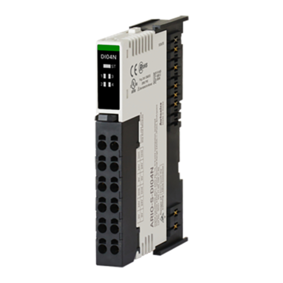
Page 11: Digital I/O Module [Ario-S-Di/Do]
2 Digital I/O module [ARIO-S-DI/DO] 2 Digital I/O module [ARIO-S-DI/DO] Be sure to see the “Instruction Manual of ARIO Series” to install the module. Failure to follow this instruction may result in malfunction and product damage. Specifications Type Digital input module... - Page 12 ※ For connecting the modules, consider power concumption of the sensors and drivers connected the ARIO coupler. In case of one coupler module connecting, the ARIO digital module is available to connect up to 8 units. © Copyright Reserved Autonics Co., Ltd.
-
Page 13: Dimensions
Module failure, error in module components Normal operation Internal network (ABUS) error (error in main and auxiliary MCU) (2) Channel indicator LED color Green Input / Output state No input / output © Copyright Reserved Autonics Co., Ltd. -
Page 14: Wiring Diagram
Input channel 3 Input channel 3 Field Power (24VDC) Field Power (24VDC) Field Ground (0VDC) Field Ground (0VDC) Input channel 4 Input channel 4 Field Power (24VDC) Field Power (24VDC) Field Ground (0VDC) Field Ground (0VDC) © Copyright Reserved Autonics Co., Ltd. - Page 15 Input channel 5 Input channel 5 Input channel 6 Input channel 6 Field Ground (0VDC) Field Power (24VDC) Input channel 7 Input channel 7 Input channel 8 Input channel 8 Field Ground (0VDC) Field Power (24VDC) © Copyright Reserved Autonics Co., Ltd.
- Page 16 Output channel 3 Output channel 3 Field Power (24VDC) Field Power (24VDC) N.C. (Not Connected) Field Ground (0VDC) Output channel 4 Output channel 4 Field Power (24VDC) Field Power (24VDC) N.C. (Not Connected) Field Ground (0VDC) © Copyright Reserved Autonics Co., Ltd.
- Page 17 Output channel 5 Output channel 5 Output channel 6 Output channel 6 Field Power (24VDC) Field Ground (0VDC) Output channel 7 Output channel 7 Output channel 8 Output channel 8 Field Power (24VDC) Field Ground (0VDC) © Copyright Reserved Autonics Co., Ltd.
-
Page 18: Analog I/O Module [Ario-S-Ai/Ao]
3 Analog I/O module [ARIO-S-AI/AO] 3 Analog I/O module [ARIO-S-AI/AO] Be sure to see the “Instruction Manual of ARIO Series” to install the module. Failure to follow this instruction may result in malfunction and product damage. Specifications (1) Analog input module... - Page 19 For connecting the modules, consider power concumption of the sensors and drivers connected the ARIO coupler and power modules. In case of one coupler connecting, the ARIO analog module is available to connect up to 4 units. © Copyright Reserved Autonics Co., Ltd.
-
Page 20: Dimensions
Module failure, error in module components Normal operation Internal network (ABUS) error (error in main and auxiliary MCU) (2) Channel indicator LED color Green Input / Output state No input / output © Copyright Reserved Autonics Co., Ltd. -
Page 21: Wiring Diagram
Input channel 1 – Input channel 3 – N.C. (Not Connected) N.C. (Not Connected) N.C. (Not Connected) Input channel 4 + N.C. (Not Connected) Input channel 4 – Ground / Shield N.C. (Not Connected) © Copyright Reserved Autonics Co., Ltd. - Page 22 Output channel 1 – Output channel 3 – N.C. (Not Connected) N.C. (Not Connected) N.C. (Not Connected) Output channel 4 + N.C. (Not Connected) Output channel 4 – Ground / Shield N.C. (Not Connected) © Copyright Reserved Autonics Co., Ltd.
-
Page 23: Data Display
0000 2710 0000 1388 2710 Model ARIO-S-AI□C1, ARIO-S-AO□C1 ARIO-S-AI□C2, ARIO-S-AO□C2 Input / Output current 0.000mA 10.000mA 20.000mA 4.000mA 12.000mA 20.000mA Data (dec) 10000 20000 12000 20000 Data (hex) 0000 2710 4E20 0FA0 2EE0 4E20 © Copyright Reserved Autonics Co., Ltd. -
Page 24: Temperature Input Module [Ario-S-Ai-Tc/Rtd]
4 Temperature input module [ARIO-S-AI-TC/RTD] 4 Temperature input module [ARIO-S-AI-TC/RTD] Be sure to see the “Instruction Manual of ARIO Series” to install the module. Failure to follow this instruction may result in malfunction and product damage. Specifications Type Temperature input module... - Page 25 For connecting the modules, consider power concumption of the sensors and drivers connected the ARIO coupler and power modules.In case of one coupler connecting, the ARIO analog module is available to connect up to 4 units. © Copyright Reserved Autonics Co., Ltd.
-
Page 26: Dimensions
Module failure, error in module components Normal operation Internal network (ABUS) error (error in main and auxiliary MCU) (2) Channel indicator LED color Green Input / Output state No input / output © Copyright Reserved Autonics Co., Ltd. -
Page 27: Wiring Diagram
Sensor 3: RTD B’ terminal signal N.C. (Not Connected) Sensor 4: RTD A terminal signal Sensor 4: + TC Sensor 4: RTD B terminal signal Sensor 4: – TC Sensor 4: RTD B’ terminal signal © Copyright Reserved Autonics Co., Ltd. -
Page 28: Parameter
JPt 1000 Ω -200.0 to 500.0 -2000 to 5000 Nickel 100 Ω Nickel 120 Ω -50.0 to 200.0 -500 to 2000 Nickel 1000 Ω ※1. Same as existing W5(TT). ※2. Same as existing W(TT). © Copyright Reserved Autonics Co., Ltd. -
Page 29: Power Module [Ario-P]
5 Power module [ARIO-P] 5 Power module [ARIO-P] Be sure to see the “Instruction Manual of ARIO Series” to install the module. Failure to follow this instruction may result in malfunction and product damage. Specifications (1) Slim Remote ABUS Power Module... - Page 30 Approx. 75g ( approx. 108g ) ※1. For more information on the number of I/O supply power, see “5.4 Wiring diagram.” ※ For connecting the modules, consider power concumption of the sensors and drivers connected the ARIO power module. © Copyright Reserved Autonics Co., Ltd.
-
Page 31: Dimensions
5 Power module [ARIO-P] Dimensions (Unit: mm) Power indicator Green LED Operation state Bus or I/O supply voltage is connected. Bus or I/O supply voltage is not connected. © Copyright Reserved Autonics Co., Ltd. -
Page 32: Wiring Diagram
System Power (24VDC) System Power (0VDC) N.C. (Not Connected) N.C. (Not Connected) N.C. (Not Connected) Ground / Shield System Power (24VDC) System Power (0VDC) N.C. (Not Connected) N.C. (Not Connected) N.C. (Not Connected) Ground / Shield © Copyright Reserved Autonics Co., Ltd. - Page 33 24VDC 0VDC Field Power (P) Field Power (P) Field Power (N) Field Power (N) 24VDC 0VDC 24VDC 0VDC 0VDC 24VDC 24VDC 0VDC Field Power (P) Field Power (P) Field Power (N) Field Power (N) © Copyright Reserved Autonics Co., Ltd.
- Page 34 5 Power module [ARIO-P] ARIO-P-T1 ARIO-P-T2 Terminal No. Descriptions Terminal No. Descriptions 24VDC 0VDC 24VDC 24VDC 0VDC 0VDC 24VDC 0VDC 24VDC 24VDC 0VDC 0VDC 24VDC 0VDC 24VDC 24VDC 0VDC 0VDC 24VDC 0VDC 24VDC 24VDC 0VDC 0VDC © Copyright Reserved Autonics Co., Ltd.
- Page 35 * Dimensions or specifications on this manual are subject to change and some models may be discontinued without notice.
Need help?
Do you have a question about the ARIO Series and is the answer not in the manual?
Questions and answers