Autonics ARIO-C-MR User Manual
Hide thumbs
Also See for ARIO-C-MR:
- Manual (28 pages) ,
- Product manual (4 pages) ,
- Product manual (12 pages)
Table of Contents
Advertisement
Quick Links
Advertisement
Table of Contents

Related Manuals for Autonics ARIO-C-MR


Summary of Contents for Autonics ARIO-C-MR
- Page 1 ARIO-C-MR Modbus/RTU Compatible User Manual MTO-ARIOCMRU1-V2.0-2200US...
-
Page 3: Table Of Contents
2. Overview of the ARIO-C-MR ........ - Page 4 5.2. 03 (0x03) Read Holding Register (4x)........... . ...
-
Page 5: Preface
Preface Thank you for purchasing Autonics products. Be sure to read and follow the Safety Precautions thoroughly before use. This manual contains information about the product and how to use it properly, so keep it in a place where users can easily find it. - Page 6 6 Autonics | ARIO-C-MR...
-
Page 7: Manual Guide
• Any or all of the manual may not be edited or copied without permission. • The manual is not provided with the product. • Download and use from our website (www.autonics.com). • The contents of the manual are subject to change without prior notice according to the improvement of the product’s performance, and upgrade notices are provided through our website. - Page 8 8 Autonics | ARIO-C-MR...
-
Page 9: Common Symbols In The Manual
Common Symbols in the Manual Failure to follow instructions may result in serious injury or death. Failure to follow instructions may result in injury or product damage. Supplementary explanation of the function Example of that function Important information about the feature Common Symbols in the Manual ... - Page 10 10 Autonics | ARIO-C-MR...
-
Page 11: Safety Considerations
Safety Considerations Observe all 'Safety Considerations' for safe and proper operation to avoid hazards. Warning 1. Fail-safe device must be installed when using the unit with machinery that may cause serious injury or substantial economic loss. (e.g., nuclear power control, medical equipment, ships, vehicles, railways, aircraft, combustion apparatus, safety equipment, crime/disaster prevention devices, etc.) Failure to follow this instruction may result in personal injury, fire or economic loss. - Page 12 The specifications and dimensions of this manual are subject to change without any notice for product improvement. Be sure to read and follow the considerations written in the instruction manual, other manuals, and technical information on our Autonics website. 12 Autonics | ARIO-C-MR...
-
Page 13: Reference Manuals
Be sure to read the reference manuals below to use the product correctly and follow the precautions written in these manuals. You can download the reference manuals on our Autonics website. Installation manual It contains information for you to setup and install the ARIO Unit. - Page 14 3. Software information: process images, and mapping information, etc. Module manual It contains information on the modules provided by Autonics. 1. Hardware information: specifications, indicators, connection diagram, and dimensions, etc. DAQMaster user manual It contains information and usage guides on ARIO-related functions supported by DAQMaster, the comprehensive device management program.
-
Page 15: Overview Of The Ario-C-Mr
Ethernet and Serial communication: The Modbus/RTU, a type of the Fieldbus, is the Serial-based communication designed for use with the PLC. The ARIO-C-MR supports the Modbus/RTU protocol. This coupler composes the physical structure of connected modules and devices and creates input and output process images linked with the data of Modbus/RTU. -
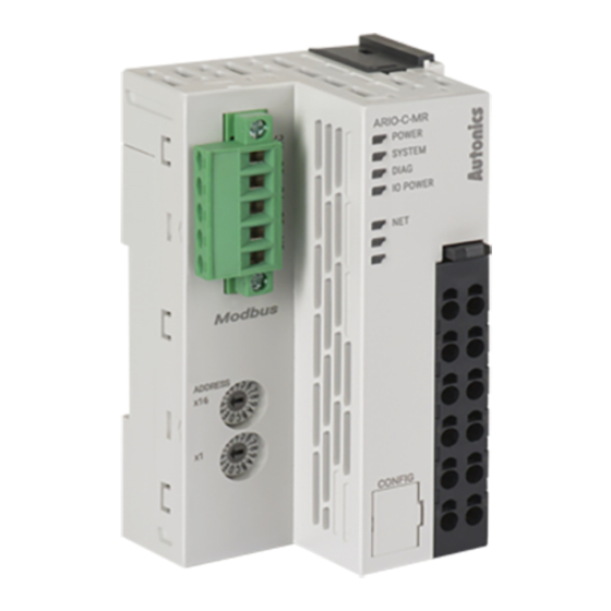
Page 16: Unit Descriptions
For detailed information on addressing method, refer to the 2.4, “Assign the Node Address”. 3. CONFIG Port It is a port to connect to the PC where DAQMaster is installed. 1. Port type: USB Type-B Micro 16 Autonics | ARIO-C-MR... - Page 17 4. Indicators It displays the status of the coupler and communication connection as shown below. For detailed information on the indicators, refer to the Indicators. 1. Power and operating status of the coupler 2. Modbus communication status 5. Power Supply Terminal It is a terminal block that supplies power to the coupler and peripherals.
-
Page 18: Communication Connector
Color Description NC: Not Connected Not used DG: Data Ground Black Grounding for the signals FG: Frame Ground Shielding / Grounding DB: DATA B White RS-485 low signal DA: DATA A Blue RS-485 high signal 18 Autonics | ARIO-C-MR... -
Page 19: Assign The Node Address
2.4. Assign the Node Address • It is recommended to designate the node address of the coupler the same as the value of the rotary switches. • The node address cannot be applied while the coupler is operating. • Be sure to start the coupler again to apply the changed node address. •... -
Page 20: Set The Baud Rates
To select the baud rates in the DAQMaster, go to Comm Mode » Property tab of the coupler » Baud Rate and click the drop-down menu. Baud rates (bps) Setting values 2400 4800 9600 2 (factory setting) 19200 38400 57600 115200 20 Autonics | ARIO-C-MR... -
Page 21: Connections Of The Power Terminal
2.6. Connections of the Power Terminal Terminal no. Name Description 1, 7 System Power (24 V Power supply for the coupler, module and ABUS to be operated. • The terminals feed the power supply to the 2, 8 System Power (0 V top input contacts. - Page 22 22 Autonics | ARIO-C-MR...
-
Page 23: Indicators
3. Indicators The indicators of the ARIO-C-MR coupler consist of elements indicating the operating status for the coupler, and connection status for the field network (Modbus/RTU) as shown in the figure below. For detailed information on each indicator, refer to the following tables below. -
Page 24: Leds For The Coupler Status
The models of the replaced module and the previous one mismatch (normal operation) Flashing (2 times) No module connection (non-recoverable) Flashing (3 times) Abnormal module operation (non-recoverable) Flashing (4 times) The number of modules and data size exceeded Normal operation 24 Autonics | ARIO-C-MR... -
Page 25: Leds For The Field Network Status
4. The status of power supply for the module Indicator LED color Status Description IO POWER Green Supply voltage for the I/O signals of modules : Normal Supply voltage for the I/O signals of modules : None 3.2. LEDs for the Field Network Status 1. - Page 26 Refer to the timing chart below for the flashing operation of indicators. The operation is repeated as flashing every 200 microseconds and standby for 1 second. 26 Autonics | ARIO-C-MR...
-
Page 27: Process Images
4. Process Images 4.1. Memory Map The ARIO unit composes the memory map in its memory space to assign and manage the data collected by the coupler and modules. The master in the field network controls the input and output devices via this memory map generated by the ARIO unit. -
Page 28: Data Processing In The Module
4 channels/module (4-CH/module) 1-byte 8 channels/module (8-CH/module) 1-byte 16 channels/module (16-CH/module) 2-byte (= 1-word) Analog input/output 8-bit/channel (8-bit/CH) 1-byte : Byte-oriented 12-bit/channel (12-bit/CH) 2-byte (= 1-word) 16-bit/CH (16-bit/CH) 2-byte (= 1-word) 24-bit/channel (24-bit/CH) 4-byte (= 2-word) 28 Autonics | ARIO-C-MR... -
Page 29: Check The Data Of The Modules
4.2.1. Check the Data of the Modules You can check the data of modules connected with the coupler as shown in the figure below. To check the data, go to Comm Mode » » I/O Monitor in the DAQMaster. The binary, decimal, and hexadecimal are supported as the display format in the DAQMaster. 1. -
Page 30: Example Of The Process Image
16 bits (1 word). The process image of the Modbus protocol is expressed as big-endian (MSB → LSB) of 16 bits and consists of the input register and holding register. DAQMaster: An arrangement example of the ARIO unit 30 Autonics | ARIO-C-MR... - Page 31 DAQMaster: The address map of the ARIO unit • Protocol Address (Base 0) • PLC Address (Base 1) 4.3. Example of the Process Image 31...
-
Page 32: Input Process Image
1: AO02V1 Ch.1 High Byte Ch.1 Low Byte Ch.2 High Byte Ch.2 Low Byte 4: DO04P Ch.4 Ch.3 Ch.2 Ch.1 6: DO04P Ch.4 Ch.3 Ch.2 Ch.1 8: DO08P Ch.8 Ch.7 Ch.6 Ch.5 Ch.4 Ch.3 Ch.2 Ch.1 32 Autonics | ARIO-C-MR... -
Page 33: Mapping Of The Coupler Diagnostic Data
4.3.3. Mapping of the Coupler Diagnostic Data To check the value of the coupler diagnosis in the DAQMaster, go to Comm Mode » Property tab of the coupler » Coupler State. Byte Bit 7 Bit 6 Bit 5 Bit 4 Bit 3 Bit 2 Bit 1... - Page 34 The information on the coupler state (running with SYSTEM indicator) 0: Normal state 1: Error • Cause 1: Error occurred in the coupler initialization and settings, etc. • Cause 2: Error occurred in the field network connection, etc. 34 Autonics | ARIO-C-MR...
-
Page 35: Function Codes
5. Function Codes The following tables describe the data model and public function codes for the Modbus protocol supported by the ARIO-C-MR. • Data model Modbus data Access unit Reference no. Function code Data type Input Registers Word (16-bit) Holding Registers... -
Page 36: 0X04) Read Input Register (3X)
The number of modules connected to 300126 (0x007D) the coupler 5.1.3. The Diagnostic Data of Coupler Data Register Value The diagnostic data of the coupler 301024 (0x03FF) Refer to the 4.3.3, “Mapping of the Coupler Diagnostic Data”. 36 Autonics | ARIO-C-MR... -
Page 37: The Configuration Information Of The Modbus/Rtu
5.1.4. The Configuration Information of the Modbus/RTU Data Register Value Coupler’s Baud rate 301030 (0x0405) • 0: 2400 bps • 1: 4800 bps • 2: 9600 bps • 3: 19200 bps • 4: 38400 bps • 5: 57600 bps • 6: 115200 bps Parity bit 301031 (0x0406) •... -
Page 38: 0X03) Read Holding Register (4X)
5.2.2. Read the Output Data Data Register Value The data from the output module 402001 to 402256 (0x07D0 to 0x08CF) For more information on the address of the output module, refer to the AddressMap in the DAQMaster. 38 Autonics | ARIO-C-MR... -
Page 39: 0X06) Write Single Register / 16 (0X10) Write Multiple Registers
5.3. 06 (0x06) Write Single Register / 16 (0x10) Write Multiple Registers • 06 (0x06) Write Single Register : It writes the single value with a size of 1 word (16-bit) to the holding register in the coupler. • 16 (0x10) Write Multiple Registers : It writes the multiple values with a size of 1 word (16-bit) to the holding register in the coupler. - Page 40 40 Autonics | ARIO-C-MR...
-
Page 41: Daqmaster
6. DAQMaster 6.1. Configure the Modbus/RTU • Be sure to see the version compatibility table of the ARIO Series on our Autonics website to check the software/firmware(SW) and hardware(HW) versions of the coupler and modules. • Refer to the 6.3, “Update the Firmware Version”... - Page 42 Set the positions of Hexadecimal Rotary Switches to 0x01. This chapter only describes based on our software, DAQMaster. For detailed information on communication connection and usage method with the master, refer to the user manuals provided by the specific manufacturer. 42 Autonics | ARIO-C-MR...
-
Page 43: Add Registers
6.1.2. Add Registers 1. Connect the communication connector on the ARIO-C-MR to the PC where the DAQMaster is installed. 2. Select Tool » Edit ModBus Device on the top menu of the DAQMaster. 3. Select ModBus Editor » Properties »... - Page 44 ◦ Start Address: 2001 (based on the PC) ◦ Value Type: UInt16 (0 to 65535) ◦ Signal Type: Analog fixed ◦ Value Mode: Normal ◦ Reading When Run DAQMaster: Continue Reading ◦ Others: Fixed values Example of the registers 44 Autonics | ARIO-C-MR...
- Page 45 PC. Save ◦ Vendor: Desired vendor name (e.g., Autonics) ◦ Product: Desired product name (e.g., ARIO-C-MR) ◦ Start Address: Start at 1 ◦ Communication Device: Both RS-232 and TCP/IP selected ◦ Frame cycle: 40 fixed ◦...
- Page 46 9. Right-click on the My System » RS-232 » ARIO-C-MR and select the Add. (If necessary, you can change the communication settings in the property window on the right side of the screen when the RS-232 is selected.) 46 Autonics | ARIO-C-MR...
- Page 47 10. Select the node address of coupler at the Device List and click to add it to the Used Device on the > right side of the window. Click the to add the coupler. 11. The coupler is added to My System as shown below. 6.1.
-
Page 48: Add Tags
1. When selecting the I/O List » ARIO-C-MR, the I/O registers added on the ModBus Editor are displayed. Select the register to use, right-click and select the Add to DAQ list. 2. The tags are added to the DAQ List window as shown below. - Page 49 4. Select the Project » Connect » Run. Then the green LED lights up on the NET indicator of the coupler. Check the connection status on the My System as shown below. 6.1. Configure the Modbus/RTU 49...
-
Page 50: Monitor The Data
You can see that the green LEDs light up on channel indicators 1 and 2 of the digital output module. ※ 768 = Binary 0000 0011 0000 0000 3. You can see the input data from the tag 03 Read on the Bar Graph window. 50 Autonics | ARIO-C-MR... -
Page 51: Monitor The Ario Unit
6.2. Monitor the ARIO Unit 1. Connect the CONFIG port of the ARIO coupler to the PC where the DAQMaster is installed. 2. Select the Supported Device List » AUTONICS » ARIO Config to add the ARIO coupler and then select the Connect »... - Page 52 4. The tags are added on the DAQ List window as shown below. 5. Double-click the RunTime Screen » Data » (e.g.) Multi Panel to configure the visualized monitoring screen. A multi-panel window will be created on the DAQ Space window. 52 Autonics | ARIO-C-MR...
- Page 53 6. Drag and drop the tags added on the DAQ List window to the Multi Panel window. 7. When selecting the Project » Run, you can monitor the channel status of the module. 6.2. Monitor the ARIO Unit 53...
-
Page 54: Update The Firmware Version
1. Select the to perform the update. Firmware update Without Internet connection 1. Download the latest firmware version of the coupler from the Autonics website. 2. Select the to import the downloaded .zip file. Load firmware file 3. Select the latest version of ARIO-C-MR at the Firmware version list 4. -
Page 55: Dimensions
7. Dimensions • For the detailed drawings, follow the Autonics website. • Unit: mm Coupler 7. Dimensions 55... - Page 56 End module 56 Autonics | ARIO-C-MR...
-
Page 57: Specifications
8. Specifications 8.1. Electrical/Mechanical Specifications Max. number of ≤ 32 (The length of connected modules: ≤ 384 mm) connectable modules Memory size • Input: 256-byte • Output: 256-byte Power supply • Unit (coupler + module): ≤ 9.6 W, ≤ 400 mA (≤ 200 mA/CH, 2-CH/COM) •... -
Page 58: Environmental Conditions
Ambient temperature -10 to 55 ℃, storage: -25 to 70 ℃ (no freezing or condensation) Ambient humidity 35 to 85 %RH, storage: 35 to 85 %RH (no freezing or condensation) Protection rating IP20 (IEC standard) 58 Autonics | ARIO-C-MR... -
Page 59: Communication Interface
9. Communication Interface 9.1. RS-485 Comm. standard EIA RS-485 compliant Synchronous method Asynchronous Comm. method 2-wire Half-Duplex Cable spec. The cable approved by the Modbus Organization or meets at least EIA RS-485 compliant Baud rates 2400 / 4800 / 9600 (factory setting) / 19200 / 38400 / 57600 / 115200 bps Cable length ≤... - Page 60 Dimensions or specifications on this manual are subject to change and some models may be discontinued without notice. www.autonics.com...
Need help?
Do you have a question about the ARIO-C-MR and is the answer not in the manual?
Questions and answers