
Subscribe to Our Youtube Channel
Related Manuals for Vega Absolute M-BUS-2


Summary of Contents for Vega Absolute M-BUS-2
- Page 1 LORAWAN CONVERTER M-BUS-2 USER MANUAL DOCUMENT REVISION FIRMWARE VERSION www.vega-absolute.ru...
-
Page 2: Table Of Contents
Converter operation in the universal poll mode ......................14 4 COMMUNICATION PROTOCOL – 1.1 VERSION ......................15 Converter M-BUS-2 transmits the following types of packets ................... 15 Packet with current readings from connected heat meter ................... 15 Packet with data from connected M-BUS device in universal poll mode ............16 Packet with time correction request.......................... -
Page 3: Introduction
M-BUS-2 / User Manual INTRODUCTION This manual is designated for M-BUS-2 device (hereinafter – device, converter) manufactured by Vega-Absolute OOO and provides information on powering and activation procedure, control commands and functions of the device. This manual is targeted at specialists familiar with installation work fundamentals for electronic and electrical equipment. -
Page 4: Description And Operation
M-BUS-2 / User Manual 1 DESCRIPTION AND OPERATION DEVICE DESCRIPTION The device M-BUS-2 is designed for reading of values from metering instruments via M- BUS interface and further accumulating and transmitting of this data to the LoRaWAN network. ® The converter is powered by a 6400 mAh built-in battery. - Page 5 M-BUS-2 / User Manual Vega M-BUS-2 device supports two activation methods in the LoRaWAN network - ABP ® and OTAA. One of the methods can be chosen using the «Vega LoRaWAN Configurator» application (see the "User Manual" for the program).
-
Page 6: Functional
M-BUS-2 / User Manual FUNCTIONAL M-BUS-2 converter is A class device (LoRaWAN ® classification) and has the following features: ADR support (Adaptive Data Rate) Sending of confirmed packets (configurable) Temperature measurement by the internal temperature sensor Charge measuring of the built-in battery (%) -
Page 7: Specification
M-BUS-2 / User Manual 2 SPECIFICATION DEVICE SPECIFICATION MAIN M-BUS interface Quantity of connecting M-BUS devices up to 10 USB-port mini-USB, type B Operating temperatures -40…+85 °С LoRaWAN ® LoRaWAN ® class Quantity of LoRa channels RU868, EU868, KZ865, custom... -
Page 8: Default Device Settings
M-BUS-2 / User Manual DEFAULT DEVICE SETTINGS PARAMETER VALUE Frequency plan RU868 Activation type ABP or OTAA Adaptive Data Rate (ADR) Confirmed Uplinks Rx 1 delay 1 second Join accept delay 5 seconds Uplink number of transmissions Data rate Power... -
Page 9: Operation
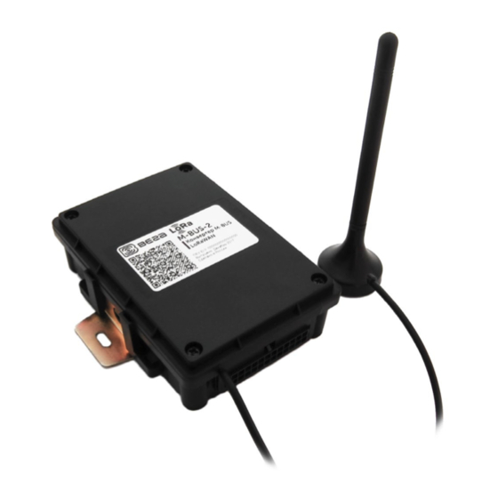
M-BUS-2 / User Manual 3 OPERATION DEVICE APPEARANCE Vega M-BUS-2 is represented in black plastic case screwed together. 1 – screws ø 3 mm х 2 – input of external antenna 3 – harness connector included 4 – screw fastening All control and indication elements are located inside the case on the board. -
Page 10: Contacts
M-BUS-2 / User Manual CONTACTS Converter has 12 contact pairs which are M-BUS interfaces. Converter provide connection up to 10 M-BUS devices. You can choose any 10 of 12 contact pairs. Wherein 1-2 contacts are M-BUS- (bot row), and 13-24 contacts are M-BUS+ (top row). -
Page 11: Mounting Recomendations
M-BUS-2 / User Manual LED SIGNAL MEANING Short flashlights Linking to the network in progress The device has been successfully One long flashing connected to the network and is in during 5 sec active mode Three flashing each by Linking to the network has been failed... - Page 12 4. Stripping wires in a bundle and connecting external equipment to them. 5. Connecting all necessary wires to the M-BUS-2 contacts. 6. M-BUS-2 converter uses an external antenna for operation. It must be connected to the dedicated connector on the device board and lead out the wire through a special groove in the case.
- Page 13 M-BUS-2 / User Manual 8. When the power is connected at the first time the device automatically switches to the “Active” mode and starts registration in the network. But if the device with connected battery or an external power has been switched to the “Storage” mode (by pressing on the start button more than 5 sec) than you need to press the button to start.
-
Page 14: Converter Operation In The Independent Poll Mode Of The Metering Devices
M-BUS-2 / User Manual CONVERTER OPERATION IN THE INDEPENDENT POLL MODE OF THE METERING DEVICES In the independent poll mode, the converter periodically and consistently polls the metering devices at their secondary addresses. The addresses of the polling devices are writting to the converter using the "Vega LoRaWAN Configurator"... -
Page 15: Communication Protocol - 1.1 Version
M-BUS-2 / User Manual 4 COMMUNICATION PROTOCOL – 1.1 VERSION This part describes the M-BUS-2 data exchange protocol with LoRaWAN network. ® In fields consisting of several bytes, the little-endian byte order is used CONVERTER M-BUS-2 TRANSMITS THE FOLLOWING TYPES OF PACKETS 1. -
Page 16: Packet With Data From Connected M-Bus Device In Universal Poll Mode
M-BUS-2 / User Manual A package of this type is transmitted separately for each connected meter. For example, if 5 metering devices are connected to the converter, 5 packets will be transferred to the next connection. «Values of basic settings» bit field decoding... -
Page 17: Settings Packet
M-BUS-2 / User Manual 4. Settings packet Transmitting on LoRaWAN port 3. ® Размер в байтах Описание поля Тип данных 1 byte Packet type, this packet == 00 uint8 2 bytes ID of parameter uint16 1 byte Data length (len) -
Page 18: Converter M-Bus-2 Receives Packets Of The Following Types
The package with settings sent to the device may not contain all the settings supported by the device, but only the part that needs to be changed. Table of ID of M-BUS-2 parameters and these possible values. ID of Description... - Page 19 M-BUS-2 / User Manual ADR (Adaptive Data Rate) 1 byte 1 – enabled 2 – disabled Uplinks number of transmissions 1 byte from 1 to 15 Communication period 1 byte 1 – 1 hour 2 – 6 hours 3 – 12 hours 4 –...
-
Page 20: Storage And Transportation Requirements
M-BUS-2 / User Manual 5 STORAGE AND TRANSPORTATION REQUIREMENTS The M-BUS-2 converter shall be stored in the original packaging in heated room at temperatures +5°С to +40°С and relative humidity less than 85%. The converter shall be transported in covered freight compartments of all types at any distance at temperatures -40°C to +85°C. -
Page 21: Content Of The Package
M-BUS-2 / User Manual 6 CONTENT OF THE PACKAGE The M-BUS-2 device is delivered complete with: Converter M-BUS-2 – 1 pc. Antenna LoRa – 1 pc. 24-pin bus – 1 pc. Factory certificate – 1 pc. Revision 10 13.10.2021... -
Page 22: Warranty
M-BUS-2 / User Manual 7 WARRANTY The manufacturer guarantees that the product complies with the current technical documentation, subject to the storage, transportation and operation conditions specified in the "User Manual". The warranty period is 36 months if the number of data packets sent by the product is up to 5,000. - Page 23 M-BUS-2 / User Manual DOCUMENT INFORMATION Title M-BUS-2 LoRaWAN converter Document type Manual - Translation from Russian Document number V02-MBUS2-01 Revision and date 10 от 13.10.2021 Revision History Revision Data Name Comments 20.12.2017 Document creation date Supported connected devices list, transparent mode is 05.04.2018...
- Page 24 M-BUS-2 / User Manual vega-absolute.ru Operation Manual © Vega-Absolute OOO 2017-2021 Revision 10 - 13.10.2021...
Need help?
Do you have a question about the M-BUS-2 and is the answer not in the manual?
Questions and answers