
Subscribe to Our Youtube Channel
Related Manuals for Vega Absolute M-BUS-1


Summary of Contents for Vega Absolute M-BUS-1
- Page 1 LORAWAN CONVERTER M-BUS-1 USER MANUAL DOCUMENT REVISION FIRMWARE VERSION 2.0 and higher www.vega-absolute.ru...
-
Page 2: Table Of Contents
Converter operation in the universal poll mode ......................17 4 COMMUNICATION PROTOCOL – 1.1 VERSION ......................21 Converter M-BUS-1 transmits the following types of packets ..................21 Packet with current readings from connected heat meter ................... 21 Packet with data from connected M-BUS device ....................22 Packet with data about external power ........................ - Page 3 M-BUS-1 / User Manual Output on command ..............................24 Converter operation in transparent mode ........................ 25 Output off command ..............................25 Packet with request of settings ........................... 25 Packet with settings is identical to such packet from device ................26 5 STORAGE AND TRANSPORTATION REQUIREMENTS ....................
-
Page 4: Introduction
M-BUS-1 / User Manual INTRODUCTION This manual is designated for M-BUS-1 device (hereinafter – device, converter) manufactured by Vega-Absolute OOO and provides information on powering and activation procedure, control commands and functions of the device. This manual is targeted at specialists familiar with installation work fundamentals for electronic and electrical equipment. -
Page 5: Description And Operation
BUS interface and further accumulating and transmitting of this data to the LoRaWAN network. ® M-BUS-1 has two ‘open-drain’ outputs so it can be used as a control device. Also, device has two security inputs. Converter M-BUS-1 may operate in two modes. Converter can be used for any utilities’... -
Page 6: Functional
The internal clock is set automatically when device connected to the "Vega LoRaWAN Configurator" throughUSB, also can be adjust via LoRaWAN network. ® FUNCTIONAL M-BUS-1 converter can either be of class A or class C (LoRaWAN classification) and ® has the following features: Revision 15 – 30 June 2021... -
Page 7: Marking
M-BUS-1 / User Manual Automatic change from A class to C class when powered from an external power supply ADR support (Adaptive Data Rate) Sending of confirmed packets (configurable) Extra communication in case of security inputs actuation Temperature measurement by the internal temperature sensor... -
Page 8: Specification
M-BUS-1 / User Manual 2 SPECIFICATION DEVICE SPECIFICATION MAIN M-BUS interface Quantity of connecting M-BUS devices up to 10 Security inputs ‘Open-drain’ outputs USB-port mini-USB, type B Operating temperatures -40…+85 °С LORAWAN ® LoRaWAN class A or С Quantity of LoRa channels... -
Page 9: Default Device Settings
M-BUS-1 / User Manual DEFAULT DEVICE SETTINGS PARAMETER VALUE RU868 Frequency plan OTAA Activation type Adaptive Data Rate Confirmed Uplinks 1 second Rx 1 Delay 5 seconds Join Accept Delay Uplink number of transmissions Data rate 14 dBm Power 24 hours... -
Page 10: Operation
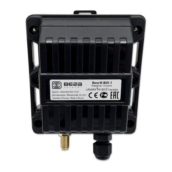
3 OPERATION DEVICE APPEARANCE Vega M-BUS-1 is represented in black plastic case which has six screws and mounting for DIN-rail. The device case is equipped with a hermetic gland of M12 size. A sealant is installed inside the gland, ensuring compliance with the declared Ingress Protection rating of the device case. - Page 11 M-BUS-1 / User Manual All of elements for manage and indication as well as connecting contacts are placed on the board inside the case. 5 – input for connecting an external antenna 6 – start button 7 – LED indicator 8 –...
-
Page 12: Contacts Description
Ʇ Ground Ground contacts 8 and 10 are used for connection of security inputs COUNT_1 and COUNT_2. Security inputs of the M-BUS-1 device are used to connect circuits with the following types of NO contacts: reed switch; mechanical pushbutton; open-collector output. - Page 13 M-BUS-1 / User Manual To increase the battery life, the physical level of the M-BUS interface is switch on (supply voltage is applied to the outputs MBAS +, MBAS-) just before meter polling with a programmable delay (the delay value is depending on the type of connected meter). The delay is introduced for initializing own meter interface and its preparing for receiving data from the converter.
-
Page 14: Led Indications
M-BUS-1 / User Manual LED INDICATIONS There is a one red LED on the board. The indication is only used when the device is activated in the LoRaWAN network and when the operating modes are changed. ® LED on the board... -
Page 15: Mounting Recomendations
5. Connecting all necessary wires to the M-BUS-1 contacts. 6. M-BUS-1 converter can be powered from an external power source as well as from a battery. For working with battery, it is necessary to connect it to battery connector on the board. - Page 16 M-BUS-1 / User Manual Contacts for connecting an Connector for external power battery source 7. When the power is connected at the first time the device automatically switches to the “Active” mode and starts registration in the network. But if the device with connected battery or an external power has been switched to the “Storage”...
-
Page 17: Converter Operation In The Independent Poll Mode
The addresses of the polling devices are written to the converter using the "Vega LoRaWAN Configurator" application. M-BUS-1 uses the secondary addresses for poll of the connected devices. The secondary address usually is equal to meter serial number. - Page 18 M-BUS-1 / User Manual Activation of the universal poll mode leads to the blocking of independent polling of supported metering devices When the “Universal poll” mode is activated, the configurator hides the menu for working with supported metering devices and displays the menu for entering user commands instead.
- Page 19 M-BUS-1 / User Manual To poll the metering device, two commands are set: • 0x10 0x40 0x45 0x85 0x16 – initialization command, the meter responds to it with a confirmation receipt 0xE5; • 0x10 0x7B 0x45 0xC0 0x16 – data request command, the meter responds to it with a packet with readings.
- Page 20 M-BUS-1 / User Manual Received data: E5 Poll meter OK Send user m-bus command: Received data: 68 54 54 68 08 45 … Poll meter OK Here Received Data: E5 – is confirmation receipt for the first command. Here Received Data: 68 54 54 68 …...
-
Page 21: Communication Protocol - 1.1 Version
M-BUS-1 / User Manual 4 COMMUNICATION PROTOCOL – 1.1 VERSION This part describes the M-BUS-1 data exchange protocol with LoRaWAN network. In fields consisting of several bytes, the little-endian byte order is used CONVERTER M-BUS-1 TRANSMITS THE FOLLOWING TYPES OF PACKETS 1. -
Page 22: Packet With Data From Connected M-Bus Device
M-BUS-1 / User Manual "Values of basic settings" bit field decoding Bits Value 0 bit Activation type 0 - OTAA, 1 – ABP Query for packet confirmation 0 – off, 1 – on Communication period: |1 == 0|2==0|3==0| - 5 minutes... -
Page 23: Packet With Data About State Changes Of The Outputs Out_1 Or Out_2
M-BUS-1 / User Manual 1 byte Battery charge, % uint8 1 byte Values of basic settings (bit field) uint8 1 byte Input number on which “Alarm” is noticed (1 or 2) uint8 1 byte Input 1 state («0» - unlocking, «1» - closure) -
Page 24: Converter M-Bus-1 Receives Packets Of The Following Types
M-BUS-1 / User Manual CONVERTER M-BUS-1 RECEIVES PACKETS OF THE FOLLOWING TYPES 1. Real-time clock adjustment Sent by application on LoRaWAN port 4. Size in bytes Field description Data type 1 byte Packet type, this packet == 255 uint8 8 bytes... -
Page 25: Converter Operation In Transparent Mode
Data uint8 Upon receiving this packet, M-BUS-1 will transfer the data contained in it to the M-BUS interface (depending on the model). If the external device connected via M-BUS interface answers within the timeout specified in the M-BUS-1 settings, the response will be transferred to the LoRaWAN network as one or more type 3 packets. -
Page 26: Packet With Settings Is Identical To Such Packet From Device
The package with settings sent to the device may not contain all the settings supported by the device, but only the part that needs to be changed. Table of ID of M-BUS-1 parameters and these possible values ID of Description... - Page 27 M-BUS-1 / User Manual 1 – Teplouchet-1 2 – STE 21 «Berill 3 – Danfoss Sonometer_500 4 – ELF_M 5 – Weser 6 – MULTICAL_801 7 – MULTICAL_402 8 – LANDIS_GYR_COMMON 9 – SHARKY_775 10 – PULSAR 11 – SONOSAFE_10 12 –...
-
Page 28: Storage And Transportation Requirements
M-BUS-1 / User Manual 5 STORAGE AND TRANSPORTATION REQUIREMENTS The M-BUS-1 converter shall be stored in the original packaging in heated room at temperatures +5 °С to +40 °С and relative humidity less than 85%. The converter shall be transported in covered freight compartments of all types at any distance at temperatures -40 °C to +85 °C. -
Page 29: Content Of The Package
M-BUS-1 / User Manual 6 CONTENT OF THE PACKAGE The M-BUS-1 device is delivered complete with: Converter M-BUS-1 (with 2 screws in the case) – 1 pc. Antenna LoRa – 1 pc. Screw 3х16 – 4 pcs. Factory certificate – 1 pc. -
Page 30: Warranty
M-BUS-1 / User Manual 7 WARRANTY The manufacturer guarantees that the product complies with the current technical documentation, subject to the storage, transportation and operation conditions specified in the "User Manual". The warranty period is 36 months if the number of data packets sent by the product is up to 10,000. - Page 31 M-BUS-1 / User Manual DOCUMENT INFORMATION Title M-BUS-1 LoRaWAN device Document type Manual - Translation from Russian Document number V02-MBUS1-01 Revision and date 15 – 30 June 2021 Revision History Revision Date Name Comments 29.08.2017 Document creation date 05.10.2017 Minor changes 26.10.2017...
- Page 32 M-BUS-1 / User Manual list of supported metering devices has been changed, the size of the black box has been increased, new functionality has been added, new warranty 30.06.2021 conditions, the exchange protocol (packet 1) has been changed, scheduled revision of documentation, new parts Revision 15 –...
- Page 33 M-BUS-1 / User Manual vega-absolute.ru User Manual © OOO Vega-Absolute 2017-2021 Revision 15 – 30 June 2021...
Need help?
Do you have a question about the M-BUS-1 and is the answer not in the manual?
Questions and answers