Table of Contents
Advertisement
Quick Links
Advertisement
Table of Contents

Related Manuals for Vega Absolute M-BUS-2


Summary of Contents for Vega Absolute M-BUS-2
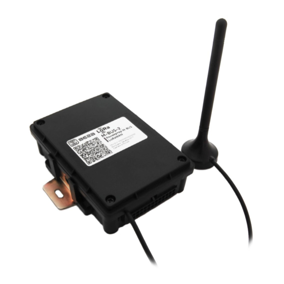
- Page 1 LORAWAN CONVERTER M-BUS-2 User Manual www.vega-absolute.ru...
- Page 2 M-BUS-2 / User Manual Document Information Title M-BUS-2 LoRaWAN converter Document type Manual - Translation from Russian Document number V02-MBUS2-01 Revision and date 09 – 06 July 2021 This document applies to the following products: Product name Type number End devices...
- Page 3 M-BUS-2 / User Manual The list of supported metering devices, volume of memory for accumulation of packages and warranty 06.07.2021 conditions are changed; support of poll at difference types of metering devices and new mode of universal poll are add.
-
Page 4: Table Of Contents
CONVERTER OPERATION IN THE UNIVERSAL POLL MODE ................. 25 5 COMMUNICATION PROTOCOL – 1.1 VERSION ......................28 Converter M-BUS-2 transmits the following types of packets ................... 28 Packet with current readings from connected heat meter ................... 28 Packet with data from connected M-BUS device in universal poll mode ............29 Packet with time correction request. - Page 5 M-BUS-2 / User Manual 6 STORAGE AND TRANSPORTATION REQUIREMENTS ....................33 7 CONTENT OF THE PACKAGE ............................. 34 8 WARRANTY ..................................... 35 Revision 09- 06 July 2021...
-
Page 6: Introduction
M-BUS-2 / User Manual INTRODUCTION This manual is designated for M-BUS-2 device (hereinafter – device, converter) manufactured by Vega-Absolute OOO and provides information on powering and activation procedure, control commands and functions of the device. This manual is targeted at specialists familiar with installation work fundamentals for electronic and electrical equipment. -
Page 7: Description And Operation
M-BUS-2 / User Manual 1 DESCRIPTION AND OPERATION DEVICE DESCRIPTION The device M-BUS-2 is designed for reading of values from metering instruments via M-BUS interface and further accumulating and transmitting of this data to the LoRaWAN network. Converter M-BUS-2 can be used for any utilities’ meters and industrial equipment with M-BUS interface including water-, electricity-, and heat meters. -
Page 8: Functional
The internal clock is set automatically when device connected to the "Vega LoRaWAN Configurator" via USB, also adjustable via LoRaWAN. FUNCTIONAL M-BUS-2 converter is A class device (LoRaWAN classification) and has the following features: o ADR support (Adaptive Data Rate) -
Page 9: Specification
M-BUS-2 / User Manual 2 SPECIFICATION Main M-BUS interface Quantity of connecting M-BUS devices up to 10 USB-port mini-USB, type B Operating temperatures -40…+85 °С LoRaWAN LoRaWAN class Quantity of LoRa channels Frequency plan RU868, EU868, IN865, AS923, AU915, KR920, US915, KZ865, custom (EU868... -
Page 10: Operation
M-BUS-2 / User Manual 3 OPERATION CONTACTS Converter has 12 contact pairs which are M-BUS interfaces. Converter provide connection up to 10 M-BUS devices. You can choose any 10 contact pairs. Wherein 1-2 contacts are M-BUS- (bot row), and 13-24 contacts are M-BUS+ (top row). -
Page 11: Initial Startup
M-BUS-2 / User Manual INITIAL STARTUP The M-BUS-2 converter is powered from the built-in battery. In case of disconnect battery, you need to connect the battery to the one of the two power connectors on the board. Power connectors The converter supports two activation methods in the LoRaWAN network - ABP and OTAA. -
Page 12: Converter Operation In The Independent Poll Mode Of The Metering Devices
M-BUS-2 / User Manual Press the start button located on the board 2. OTAA. After pressing the start button, the device makes three attempts to connect to the network within the set frequency plan. After the activation in the LoRaWAN network is confirmed, the device sends a signal (LED flashing for 5 seconds) and switches to the "Active"... -
Page 13: Converter Operation In The Universal Poll Mode
Activation of the universal poll mode leads to the blocking of independent polling of supported metering devices CONNECTING VIA USB The device M-BUS-2 adjusted with the "Vega LoRaWAN Configurator" application (See part 4). The described functionality is supported in the Configurator version 1.0.55 and higher. - Page 14 M-BUS-2 / User Manual Before connecting the device to the computer for the first time, you must install the driver for the COM port stsw-stm32102, which can be downloaded from iotvega.com. After running the executable file VCP_V1.4.0_Setup.exe, the installer window will appear: In this window, you need to click Next, then Install, and then the installation will begin.
-
Page 15: Vega Lorawan Configurator
M-BUS-2 / User Manual 4 VEGA LORAWAN CONFIGURATOR The "Vega LoRaWAN Configurator" application (hereinafter referred to as the configurator) is intended for setting up the device via USB. The configurator has two modes of operation - "Simple" and "Expert". In the "Simple"... -
Page 16: Connection To The Device
M-BUS-2 / User Manual The application window contains three tabs – Device info, LoRaWAN settings and device settings. The language selection menu is in the upper right corner. CONNECTION TO THE DEVICE For the connection to the device, perform the following steps: 1. -
Page 17: Device Info" Tab
M-BUS-2 / User Manual “DEVICE INFO” TAB The "Device info" tab displays information about the device, its current status, and also the data needed to register the device in the LoRaWAN network. ABP info - displays the data necessary to register the device in the LoRaWAN network with ABP method (Activation By Personalization). - Page 18 M-BUS-2 / User Manual Update firmware - allows you to select the firmware file from your computer's hard drive and load it into the device. The device will automatically disconnect from the configurator when the download is complete. The current version of the device firmware can be downloaded from iotvega.com.
-
Page 19: Lorawan Settings" Tab
M-BUS-2 / User Manual “LORAWAN SETTINGS” TAB The "LoRaWAN Settings" tab allows you to configure various parameters of the LoRa network. Region - allows you to select one of installed frequency plans or specify a custom frequency plan. Custom frequency plan is EU-868 based. - Page 20 M-BUS-2 / User Manual If you select "Custom" in the "Region" field, you must manually specify the frequencies that the device will use. To do this, click the "Edit" button, the channel frequency editing window will appear: This frequency plan allows you to set up to 16 channels, as well as the frequency and speed of the second receiving window.
- Page 21 M-BUS-2 / User Manual RX1 offset (not displayed in the "Simple" mode) – specifies the time between end of packet transmission and first receiving window opening. The second receiving window always opens after 1 second after the first. Join accept delay 1 (not displayed in the "Simple" mode) – sets the time that the device will open the first receiving window to receive confirmation for the join request from the LoRaWAN network.
- Page 22 M-BUS-2 / User Manual Uplink number of transmission (not displayed in the "Simple" mode) – if the "Confirmed uplinks" function is disabled, the device will simply send each packet as many times as specified in this option. If "Confirmed uplinks" is enabled, the device will send packets until it receives a confirmation or until it sends as many packets as specified in this option.
-
Page 23: Mbus-2" Tab
M-BUS-2 / User Manual «MBUS-2» TAB The “MBUS-2” tab contains the settings of the connected device. Information on the tap is depended on version of firmware at converter. On firmware younger version 2.0 is not ability a choice different at types of metering devices, therefore for them are active only the entry field address of devices and the choice of common type at metering devices. - Page 24 M-BUS-2 / User Manual Current state – displays the current parameters of the device - the internal temperature of the device and the battery level. M-BUS settings – allows to setting M-BUS interface, set the model and addresses of connected heat meters. M-BUS-1 uses the secondary addresses for poll of the connected devices.
-
Page 25: Converter Operation In The Universal Poll Mode
M-BUS-2 / User Manual CONVERTER OPERATION IN THE UNIVERSAL POLL MODE For activate a universal poll mode is necessary to set the checkbox “universal poll”. In this mode the configurator hides the menu for working with supported metering devices and displays the menu for entering user commands instead. - Page 26 M-BUS-2 / User Manual to the second or third commands. The first one or two commands can be initialization commands, to which responses are received in the form of a confirmation receipt. Data received in the universal poll mode is transmitted in a format which similar to the...
- Page 27 M-BUS-2 / User Manual With this configuration, the work will proceed as follows: every hour, two commands will be transmitted one after the other. Only the second command will be sent to the server via the radio channel, so the confirmation receipt 0xE5 will not be sent.
-
Page 28: Communication Protocol - 1.1 Version
M-BUS-2 / User Manual 5 COMMUNICATION PROTOCOL – 1.1 VERSION This part describes the M-BUS-2 data exchange protocol with LoRaWAN network. In fields consisting of several bytes, the little-endian byte order is used CONVERTER M-BUS-2 TRANSMITS THE FOLLOWING TYPES OF PACKETS 1. -
Page 29: Packet With Data From Connected M-Bus Device In Universal Poll Mode
M-BUS-2 / User Manual A package of this type is transmitted separately for each connected meter. For example, if 5 metering devices are connected to the converter, 5 packets will be transferred to the next connection. "Values of basic settings" bit field decoding... -
Page 30: Settings Packet
M-BUS-2 / User Manual 4. Settings packet Transmitting on LoRaWAN port 3 when settings request command received, or device connected to the network Size in bytes Field description Data type 1 byte Packet type, this packet == 00 uint8 2 bytes... -
Page 31: Converter M-Bus-2 Receives Packets Of The Following Types
The package with settings sent to the device may not contain all the settings supported by the device, but only the part that needs to be changed. Table of ID of M-BUS-2 parameters and these possible values ID of Description... - Page 32 M-BUS-2 / User Manual 2 – 6 hours 3 – 12 hours 4 – 24 hours 5 – 5 minutes 6 – 15 minutes 7 – 30 minutes MBUS interface speed 1 byte 1 – 300 2 – 600 3 – 1200 4 –...
- Page 33 M-BUS-2 / User Manual 6 STORAGE AND TRANSPORTATION REQUIREMENTS The M-BUS-2 converter shall be stored in the original packaging in heated room at temperatures +5°С to +40°С and relative humidity less than 85%. The converter shall be transported in covered freight compartments of all types at any distance at temperatures -40°C to +85°C.
- Page 34 M-BUS-2 / User Manual 7 CONTENT OF THE PACKAGE The M-BUS-2 device is delivered complete with: Converter M-BUS-2 – 1 pc. Antenna LoRa – 1 pc. 24-pin bus – 1 pc. Factory certificate – 1 pc. Revision 09 - 06 July 2021...
- Page 35 M-BUS-2 / User Manual 8 WARRANTY The manufacturer guarantees that the product complies with the current technical documentation, subject to the storage, transportation and operation conditions specified in the "User Manual". The warranty period is 36 months if the number of data packets sent by the product is up to 5,000.
- Page 36 M-BUS-2 / User Manual vega-absolute.ru Operation Manual © Vega-Absolute OOO 2017-2021 Revision 09 - 06 July 2021...
Need help?
Do you have a question about the M-BUS-2 and is the answer not in the manual?
Questions and answers