
Subscribe to Our Youtube Channel
Related Manuals for Vega Absolute TP-11


Summary of Contents for Vega Absolute TP-11
- Page 1 LORAWAN CONVERTER ® VEGA TP-11 USER MANUAL DOCUMENT REVISION FIRMWARE VERSION www.vega-absolute.ru...
-
Page 2: Table Of Contents
Mounting Recomendations ..............................15 4 COMMUNICATION PROTOCOL – version 2.0 ........................17 Converter TP-11 transmits the following types of packets .................... 17 Packet with current readings ............................17 Packet with data about state changes of the outputs OUT_1 or OUT_2 ............... 18 Packet with time correction request.......................... -
Page 3: Introduction
Vega TP-11 / User Manual INTRODUCTION This manual is designated for Vega TP-11 device (hereinafter – device, converter) manufactured by Vega-Absolute OOO and provides information on powering and activation procedure, control commands and functions of the device. This manual is targeted at specialists familiar with installation work fundamentals for electronic and electrical equipment. -
Page 4: Device Purpose And Operation Principal
Converter is an autonomic device and provides connected sensors with 24 V power via 4-20 mA interface. Vega TP-11 has two ‘open-drain’ outputs so it can be used as a control device. Also, device has two security inputs. OPERATION ALGORITHM Vega TP-11 operates in modes listed below: “Storage”... - Page 5 Vega TP-11 / User Manual the "Active" mode. If all attempts fail, the device will continue to accumulate data and will attempt to connect to the network every 6 hours. Hold the start button pressed (min. 5 seconds) to switch the device from the "Active"...
-
Page 6: Functional
LoRaWAN ® network. FUNCTIONAL Vega TP-11 converter can be either of class A or class C (LoRaWAN classification) and has the following features: Automatic change from A class to C class when powered from an external power supply... -
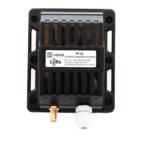
Page 7: Marking
Vega TP-11 / User Manual MARKING Device marked with sticker that contain the next information: Device model; DevEUI; Month and year of manufacture. Sticker located in three places – on device case, in factory certificate and on the packing box. -
Page 8: Specification
Vega TP-11 / User Manual 2 SPECIFICATION DEVICE SPECIFICATION MAIN Current loop 4-20 mA interface Security inputs ‘Open-drain’ outputs Accuracy of current measurement ±1.2 % USB-port mini-USB, type B Operating temperatures -40…+85 °С LORAWAN ® LoRaWAN class A or С... -
Page 9: Default Device Settings
Vega TP-11 / User Manual DEFAULT DEVICE SETTINGS PARAMETER VALUE RU868 Frequency plan OTAA Activation type Adaptive Data Rate Confirmed Uplinks 1 second Rx 1 Delay 5 seconds Join Accept Delay Uplink number of transmissions Data rate 14 dBm Power... -
Page 10: Operation
3 OPERATION DEVICE APPEARANCE Vega TP-11 is represented in black plastic case which has six screws and mounting for DIN-rail. The device case is equipped with a hermetic gland of M12 size. A sealant is installed inside the gland, ensuring compliance with the declared Ingress Protection rating of the device case. - Page 11 Vega TP-11 / User Manual All of elements for manage and indication as well as connecting contacts are placed on the board inside the case. 5 – input for connecting an external antenna 6 – start button 7 – LED indicator 8 –...
-
Page 12: Contacts
Vega TP-11 / User Manual CONTACTS Converter has 10 contacts, see table below: Contact Designation on the board Description OUT_2 Open-drain output 2 OUT_1 Open-drain output 1 +VPWR Power “+” Ʇ Power “-“ 4-20 mA “-“ 4-20 mA “+” COUNT_2 Security input 2 Ʇ... - Page 13 Vega TP-11 / User Manual For connect an external sensor contacts CL+ и CL- are used. Connection scheme see on the picture below. To save the battery life of the converter, the 24 V supply voltage is not continuously supplied. The 24 V voltage is applied to the 4-20 mA device a few seconds before the polling is performed so that the sensor can turn on and set the current corresponding to the measured parameter.
-
Page 14: Indication
Vega TP-11 / User Manual INDICATION There is a one red LED on the board. The indication is only used when the device is activated in the LoRaWAN network and when the operating modes are changed. LED on the board... -
Page 15: Mounting Recomendations
5. Connecting all necessary wires to the TP-11 contacts. 6. TP-11 converter can be powered from an external power source as well as from a battery. For working with battery, it is necessary to connect it to battery connector... - Page 16 Vega TP-11 / User Manual on the board. For working with external power source you should use the contacts +VPWR and Ʇ. Contacts for connecting an Connector for external power battery source 7. When the power is connected at the first time the device automatically switches to the “Active”...
-
Page 17: Communication Protocol - Version 2.0
Vega TP-11 / User Manual 4 COMMUNICATION PROTOCOL – version 2.0 This part describes the TP-11 data exchange protocol with LoRaWAN network. ® In fields consisting of several bytes, the little-endian byte order is used CONVERTER TP-11 TRANSMITS THE FOLLOWING TYPES OF PACKETS 1. -
Page 18: Packet With Data About State Changes Of The Outputs Out_1 Or Out_2
Vega TP-11 / User Manual 6 bit reserve (always 0) 7 bit reserve (always 0) 2. Packet with data about state changes of the outputs OUT_1 or OUT_2 Size in bytes Field description Data type 1 byte Packet type, this packet == 5... -
Page 19: Converter Tp-11 Receives Packets Of The Following Types
Output ON for the time in seconds (1…255), (0 – forever uint8 ON). Upon receiving this package TP-11 will close the correspond output and transmits the packet with current readings. 3. Output OFF command Send by application on LoRaWAN port 2. -
Page 20: Packet With Request Of Settings
The package with settings sent to the device may not contain all the settings supported by the device, but only the part that needs to be changed. Table of ID of TP-11 parameters and these possible values ID of Description... - Page 21 Vega TP-11 / User Manual 3 – short and open Guard input 2, Send alarm message 1 byte 1 – on short 2 – on open 3 – short and open Sensor startup time 1 byte From 1 to 255...
-
Page 22: Storage And Transportation Requirements
Vega TP-11 / User Manual 5 STORAGE AND TRANSPORTATION REQUIREMENTS Vega TP-11 shall be stored in the original packaging in heated room at temperatures +5 °С to +40 °С and relative humidity less than 85%. The converter shall be transported in covered freight compartments of all types at any distance at temperatures -40 °C to +85 °C. -
Page 23: Content Of The Package
Vega TP-11 / User Manual 6 CONTENT OF THE PACKAGE Vega TP-11 device is delivered complete with: Converter Vega TP-11 – 1 pc. Antenna LoRa – 1 pc. Screw 3х16 – 6 pcs. Factory certificate – 1 pc. Revision 12 of 12 October 2021... -
Page 24: Warranty
Vega TP-11 / User Manual 7 WARRANTY The manufacturer guarantees that the product complies with the current technical documentation, subject to the storage, transportation and operation conditions specified in the "Operation Manual". The warranty period for device is 36 months. - Page 25 Vega TP-11 / User Manual Revision 12 of 12 October 2021...
- Page 26 External devices connection was added Changes in the communication protocol: "Values of 10.01.2018 basic settings" bit field decoding table corrected Changes in parts “Contacts” and “Vega TP-11” tab”. An 19.06.2018 accuracy of current measurement added at the specification Communication period...
- Page 27 Vega TP-11 / User Manual vega-absolute.ru Operation Manual © Vega-Absolute OOO 2017-2021 Revision 12 of 12 October 2021...
Need help?
Do you have a question about the TP-11 and is the answer not in the manual?
Questions and answers