Table of Contents
Advertisement
Advertisement
Table of Contents

Related Manuals for Himiway COBRA


Summary of Contents for Himiway COBRA
- Page 1 O w n e r ' s M a n u a l https://himiwaybike.com...
- Page 2 Take down your serial numbers here! (Go to page 16 Bike frame number Battery serial number Motor serial number If you reset a security passcode via Display Setting, we suggest you write it down here in case you may forget:...
- Page 3 This manual contains details of the product, information on its operation and maintenance, and other helpful tips for owners. Read it carefully and familiarize yourself with the Himiway Bike before using it to ensure safe use, reduce risk of damage and premature wear, and prevent accidents. Be sure to retain this manual as your convenient Himiway Bike information source.
-
Page 4: Table Of Contents
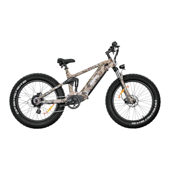
Contents • • • • • • • • • • • • • • • • • • • • • • • • • • • • • • • • • • • • • • • • • • • • • • • • • • • • • • • • • • • • • • • • • • • • • • • • • • • • • • • • • • • • • • • • • • • • • • • • • • • • • • • • • • • • • • • • • • • • • • • • • • • • • • • • • • • • • • • • • • • • • • • • • • • • • • • • • • • • • • • • • • • • • • • • • • • • • • • • • • • • • • • • • • • • • • • • • • • • • • • • • • • • • • • • • • • • • • • • • • • • • • • • • • • • • • • • • • • • • • • • • • • Bike Assembly Guide •... - Page 5 Shimano Shift Lever Power Switch LED Light Switch Information LCD Display Throttle Saddle Rear Shock Battery Head Tube Rear Brake LED Headlight Front Suspension Fork / Motor Front Shock Front Brake Rear Derailleur Controller...
- Page 6 82.6 Inch - Total Length 42.9 Inch - Handlebar Height 51.1 Inch - Wheelbase 30.3 Inch - Min Seat Height 37 Inch - Max Seat Height 19.7 Inch - Chain Stay Length 32 Inch - Standover Height 24 Inch - Top Tube Length 30.3 Inch - Wheel Diameter 5.1 Inch...
- Page 7 US standard 3.0 A smart charger 48V 20Ah Samsung/LG lithium battery 60-80 miles 48V/22A 750W brushless gear hub motor LCD display with USB charging 400 lbs 88 lbs Recommended 5'3" ~ 6'4" 0~5 level pedal assist 26" x 4.8" CST fat tires Half twist throttle Aluminum alloy comfort grip levers with motor Alloy front suspension fork with lockout and...
-
Page 8: Bike Assembly Guide
Reduce the weight of the ebike to make it easier to maneuver the bike while assembling. Avoid battery damage during the assembly process. Go to page to learn about removing and charging the battery. *Follow our Youtube channel/ Facebook "Himiway Bike" to be alerted to Himiway news, including our tutorial videos coming soon! -
Page 9: Recommended Torque Values
Hardware Location Recommended Torque(NM) Handlebar 12-18 Stem 12-18 Saddle 12-18 15-22 Rear wheel 30-38 Bottom Bracket Parts 30-50 Pedals 28-33 Disk Mounting Bolts Disk Caliper Mount Crank Bolts 32-36 Rear Derailleur Cable Pinch Front Derailleur Clamp Saddle Post Clamp NOTICE: Using an impact driver to achieve the required torque is not recommended as it might cause damage. -
Page 10: Assembly Instructions
Assembly Instructions ( ) ◆ Step 1: Loosen the bolts on your bike stem. Step 2: Center your handlebars and rotate them to align to the marking pointed to in the below image. Step 3: Tighten bolts to handlebar stem, but don’t tighten completely as you may want to further adjust the angle later to align more precisely. Test the positioning, and adjust the handlebar to your preferred angle. - Page 11 ◆ Step 1: Loosen the bolts of the protection bar of the front fork. Pull out the red pad, which is used to protect the hydraulic brake caliper. Step 2: Roll the wheel in between the front fork. Align the fork dropouts with the axle of the wheel hub, making sure the dropouts are fully seated on the axle. Also, ensure the brake rotor is properly inserted into the caliper.
- Page 12 Step 4: Install the quick-release skewer starting from the brake rotor side of the wheel, inserting the quick-release skewer through the hub, and then replacing the second cone spring on the other side. Ensure both springs are pointed narrow-side-in towards the wheel hub. Step 5: Tighten the thumb nut until the quick-release lever is held in line with the axle, and then use your palm of your hand to close the quick-release lever.
- Page 13 Step 6: Step 7: Rotate the front wheel. Make sure to fully close the quick release skewer lever on the front wheel and check the wheel balance in Pedal Only Mode. If you notice the riding is imbalanced or the rotation of the front wheel makes noise, it means the bolts were not completely tightened or not aligned horizontally.
- Page 14 ◆ Step 1: Loosen the bolts on the fork brace. While holding the nut with a 10mm wrench, unscrew the bolt with a 4mm hex wrench. Step 2: Align the bolt holes of both your front light and the front fender together with the hole on the fork brace, then reinsert the bolt through all holes and tighten the bolt with a 10mm wrench and a hex wrench.
- Page 15 ◆ Before you install the pedals, apply a small amount of waterproof grease onto the spindle. Start threading the pedal on by hand to ensure the pedal is going in perfectly straight, rotating in the direction of the pointer shown on the crank. If it is not spinning smoothly, make doubly sure that you have each pedal on...
- Page 16 ◆ Open the seatpost quick release lever. Adjust the seatpost height by sliding the seatpost up or down to a height appropriate for your leg length and preferred riding position. Do not extend the seatpost beyond the minimum insertion marking etched onto the seatpost. WARNING: Overextending the seatpost can cause it to break or come off your bike, putting you at very high risk of serious injury or death.
- Page 17 Step 1: Loosen the seat adjustment bolt beneath the seat. Move the seat backward or forward and tilt to adjust the angle within the limit markings etched on the seat rail. Do not exceed the limit markings, to ensure the safety of yourself and the bike. Step 2: Tighten the seat adjustment bolt.
- Page 18 ◆ Please write down the serial numbers found on the head tube, battery and motor on the inside front cover of this manual to facilitate failure reporting. Make sure each letter and number is correct. Make sure you take down the Capital Letters here! Make sure you take down the Capital Letters here! Bike frame number Battery serial number...
-
Page 19: Safety Check
o Test front and rear brakes for proper function. o Ensure brake pads are not overworn and are correctly positioned in relation to rims. Brakes o Make sure brake control cables are lubricated, correctly adjusted and display no obvious wear. o Check that brake control levers are lubricated and tightly secured to handlebars. -
Page 20: Safety Precautions
Safety Precautions The following safety notes provide additional information on the safe operation of your Himiway bike and should be closely reviewed. Improper operation, or ◆ • provided and should also be read before use. • Ensure you understand all instructions and safety notes/warnings. -
Page 21: Basic Display Settings
Himiway E-Bike Use and Care The following table of contents provides general guidance on Himiway e-bike variable power assist settings and their effects on both range and perfor- maintenance, etc. While Himiway hopes and believes you will thoroughly enjoy your e-bike, no guarantees of universal performance characteristics for all owners can be given. - Page 22 ◆ Power Output Battery Level Pedal Assist Level Motor Power Speed Lighting Indicator Speed Unit Function List (Check form 1 down below) Range / Time Unit Text Display Abnormal Current Throttle Fault Trip time indication Motor Phase Problem Error code indication Motor Hall Defect Brake Failed or Brake Applied While Turning ON Average speed...
- Page 23 ◆ Press and hold the power button “ ” on the control panel for two seconds until the display comes on. Press the information button “ ” on the control panel to cycle through the display settings: odometer, trip meter, max speed, and average speed. MILE MILE MILE...
- Page 24 NOTICE: If the motor power ever becomes too strong for riders’ preference or sense of safety, simply apply the handbrake to cut off motor power completely. If the throttle assist seems accidentally engaged too easily, causing unwanted acceleration, simply apply the handbrake or lower the Pedal Assist level to 0 to disengage the throttle.
- Page 25 ◆ To adjust, hold both “ + ” and “ - ” together for two seconds, bringing you to the trip meter reset screen described above. Then, hold both “ + ” and “ - ” together again for two seconds, bringing you to the Passcode screen (“ P 0510.
- Page 26 The e-bike ships with the throttle set to accelerate the e-bike to a maximum speed of 25 mph. This can be adjusted higher, BUT please be mindful of local laws and regulations regarding maximum throttle speeds permitted. Himiway is not liable for any consequences of rider misuse of maximum throttle speed adjustments.
- Page 27 ◆ To prevent theft or unauthorized use of your e-bike, you may set a security passcode to prevent use of the motor/electronics (though still permitting manual Hold “ + ” and “ - Then, hold “ - ” and “ ”...
- Page 28 Display will then show “ PSd-n + ” to change it to “ PSd-y Then, choose a 4-digit passcode of your preference. Press “ + ” and “ - ” to adjust numbers up/down. • • Hold “ ” for two seconds to return to the “ PSd-y ” screen. Hold “...
-
Page 29: Battery Charging
Battery Charging ◆ Step 1: Check the battery power indicator on your display. Step 2: Figure 1 Figure 2 Step 3: Step 4: NOTICE: This order helps extend the battery life and effectively reduces battery damage caused by improper charging. - Page 30 ◆ Step 1: Figure 3 Figure 4 NOTICE:...
- Page 31 Step 2: Figure 5 Figure 6...
- Page 32 Step 3: Light Status Charging Status Red (on charger) Charging Green(on charger) Fully charged Yellow(on battery) 40%-60% power Red(on battery) 40%< power Figure 7 Figure 8 NOTICE: failure reporting. Products that have the serial number and/or barcode removed, defaced, damaged, altered, or made illegible will not be covered by the warranty.
- Page 33 Step 4: Safest way to charge your battery- damage caused by improper charging. The charger works on 110/220 V 56/60 Hz standard home AC power outlets. Do not open the charger to select voltage input as the charger can automatically detect and account for incoming voltage. Project Unit Minimum...
- Page 34 • Longer-than-expected charge time • Strange smell, smoke, or liquid emanating from battery and/or charger • Overheating battery and/or charger Please stop charging and contact Himiway Bike immediately. ◆ • The battery can be recharged on or off the bike.
- Page 35 • after use in high-temperature weather. NOTICE: with the altered battery or motor, it will not be covered under Himiway's warranty. ◆ Please refer to the instruction manual in the charger box.
-
Page 36: Riding Modes
Himiway Cobra can reach speeds of up to 25 miles per hour with throttle mode, which not only allows you to travel faster, but also reassures riders with extra compromising comfort or safety, the throttle-assisted Himiway would be your perfect companion. -
Page 37: Riding Limitations
◆ In this mode, the Himiway will perform like a normal bike, as you’ll be riding without any assistance from the motor. This mode is especially useful if you run out of battery, or are looking for more intensive resistance training. -
Page 38: Parking & Transport
• Make sure to not park, store or transport your Himiway Bike on a rack that is not designed for the size and weight of the bike. When storing or carrying your bike on a rack for transport, remove the battery to reduce the weight and make lifting or loading easier. -
Page 39: Safety And Care Instructions
Safety and Care Instructions To ensure safe riding conditions and maximize e-bike longevity, you must follow the guidelines outlined below: • To clean the e-bike, wipe the frame with a damp cloth soaked in a mild, non-abrasive, non-corrosive detergent mixture. Wipe or spray all unpainted parts with anti-rust treatment after being used in coastal areas or areas with salty air or water. - Page 40 Maintenance ◆ Don't fully drain your battery. Turn off the power when the battery charge is low. Fully charge the battery after each use, no matter how much power is used. This will prolong the battery life. If the battery is not used for a long time, store the battery with a full charge and charge it once a month.
- Page 41 ◆ Check the pads for wear or contamination. Check the hose for cracking, wear or deformation. Replace if necessary. Check if the brake system is operating correctly. Check the pads for wear or contamination. Check the hose for cracking, wear or deformation. Replace if necessary. Check if the brake system is operating correctly.
- Page 42 5. Bleed The System You should always bleed the system after you have shortened or replaced the hose or have opened the system to the air at any time. Additionally, if the brake action feels spongy, you may improve performance by re-bleeding the system. Tools and equipment required: - 2mm Allen wrench - Piece of tubing...
- Page 43 Step 1: Step 2: Remove disc brake pads to avoid contamination during the bleed procedure. -Insert a disc brake piston setting tool or other non-sharp tool and push the pistons back into the caliper. Step 3: Insert Tektro bleed block into caliper. Bleed block ensures that pistons will not move inward during bleed procedure. Step 4: Step 5: caliper bleed port.
- Page 44 Step 8: Step 9: plug. Tighten to 2-4Nm. Step 10: bleed plug. Tighten to 2-4Nm. Step 11: Wipe off any excess oil from the lever and caliper body. Step 12: Remove 2-Piston Bleed Block and reintstall the brake pads.
- Page 45 4f. Tool free reach adjustment type-by the reach adjustment knob on the lever. 4g. By tightening the 2 mm reach-adjuster bolt on the lever. WARNING: TEKTRO had implemented 2 key improvements this year for better performance, 2.3mm thickness rotors and 5.0mm brake pads.
- Page 46 Warranty https://himiwaybike.com/pages/warranty...
- Page 47 After-sales Mail: customers@himiwaybike.com Suggestion Box: mike@himiwaybike.com...
Need help?
Do you have a question about the COBRA and is the answer not in the manual?
Questions and answers