Table of Contents
Advertisement
Advertisement
Table of Contents

Related Manuals for Himiway COBRA PRO


Summary of Contents for Himiway COBRA PRO
- Page 1 C O B R A P R O O w n e r ' s M a n u a l https://himiwaybike.com...
- Page 2 Take down your serial numbers here! Bike frame number Battery serial number Motor serial number If you reset a security passcode via Display Setting , we suggest you write it down here in case you may forget:...
- Page 3 This manual contains details of the product, information on its operation and maintenance, and other helpful tips for owners. Read it carefully and familiarize yourself with the Himiway Bike before using it to ensure safe use, reduce risk of damage and premature wear, and prevent accidents. Be sure to retain this manual as your convenient Himiway Bike information source.
-
Page 4: Table Of Contents
• • • • • • • • • • • • • • • • • • • • • • • • • • • • • • • • • • • • • • • • • • • • • • • • • • • • • • • • • • • • • • • • • • • • • • • • • • • • • • • • • • • • • • • • • • • • • • • • • • • • • • • • • • • • • • • • • • • • • • • • • • • • • • • • • • • • • • • • • • • • • • • • • • • • • • • • • • • • • • • • • • • • • • • • • • • • • • • • • • • • • • • • • • • • • • • • • • • • • • • • • • • • • • • • • • • • • • • • • • • • • • • • • • • • • • • • • Himiway E-Bike Use and Care •... -
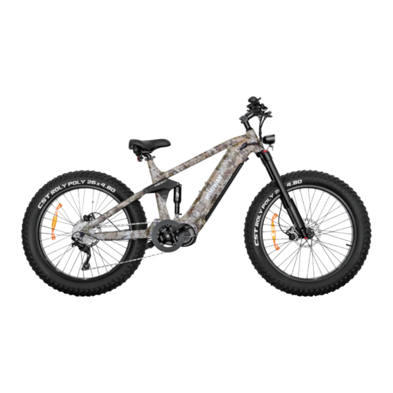
Page 5: Bike Specification
Bike Specification LCD Color Display Shimano Shifter On/Off Switch LED Light Switch Information Throttle Saddle Frame Battery Head Tube LED Head Light Front Fork Rear Brake Front Brake Real Derailleur Motor Pedal... - Page 6 82.6 Inch - Total Length 42.9 Inch - Handlebar Height 51.1 Inch - Wheelbase 30.3 Inch - Min Seat Height 37 Inch - Max Seat Height 19.7 Inch - Chain Stay Length 32 Inch - Standover Height 24 Inch - Top Tube Length 30.3 Inch - Wheel Diameter 5.1 Inch...
- Page 7 Battery Charger 48V 20Ah Samsung/LG lithium battery US standard 3.0 A smart charger Range 60-80 miles Controller 48V/30A Hub Motor Display 1000W mid-drive motor LCD display with USB charging Total Payload 400 lbs Weight 88 lbs Capacity Recommended Pedal Assist 5'3"...
-
Page 8: Bike Assembly Guide
Reduce the weight of the ebike to make it easier to maneuver the bike while assembling. Avoid battery damage during the assembly process. Go to page to learn about removing and charging the battery. *Follow our Youtube channel/ Facebook "Himiway Bike" to be alerted to Himiway news, including our tutorial video coming soon! -
Page 9: Recommended Torque Values
Recommended Torque Values Hardware Location Recommended Torque(NM) Handlebar 12-18 Stem 12-18 Saddle 12-18 Front Wheel(For bikes with bolts on front wheel) 15-22 Rear wheel 30-38 Bottom Bracket Parts 30-50 Pedals 28-33 Disk Mounting Bolts Disk Caliper Mount Crank Bolts 32-36 Rear Derailleur Cable Pinch Front Derailleur Clamp Saddle Post Clamp... -
Page 10: Assembly Instructions
Assembly Instructions Handlebar Installation(4mm Hex Wrench) ◆ Step 1: Loosen the bolts on your bike stem. Step 2 Center your handlebars and rotate them to align to the marking pointed to in the below image. Step 3: Tighten bolts to handlebar stem, but don’t tighten completely as you may want to further adjust the angle later to align more precisely. Test the positioning, and adjust the handlebar to your preferred angle. - Page 11 Front Wheel Installation ◆ Step 1: Lay a mat down to protect both bike and floor from scratches. Next, carefully flip your bike upside down for the front wheel installation. Step 2: Remove the plastic axle guards from the front wheel, being careful to avoid contact with the brake rotor set.
- Page 12 Step 3: Loosen the side bolts securing the hub axle. Using your hex key, remove the side bolt. Step 4: Slide the hub axle out. Pull out the red pad, which is used to protect the hydraulic brake caliper.
- Page 13 Step 5: Align the fork dropouts with the axle of the wheel hub, making sure the dropouts are fully seated on the axle. Also ensure the brake rotor is properly inserted into the caliper. Step 6: Reinsert the hub axle in the same direction as before, making sure the end with the bolt thread will be closest to the red suspension adjustment knob. Then reinsert the bolt into the hub axle and tighten, also tighten the two nearby bolts securing the bracket as shown in the image.
- Page 14 Step 7: Make sure the newly-installed front wheel spins freely and evenly. Front Light & Taillight Installation(Extra Tool: 10mm Wrench) ◆ Step 1: Secure the front light and tighten the nut with your 10mm wrench. Then connect the light wire connectors together. Pay careful attention to the arrows to on the wire connectors, making sure the arrows align with each other to avoid damaging the interior circuitry.
- Page 15 Step 2: Pull the hook down to lock the taillight to the steel spring. Pedals Intallation ◆ Make sure your pedals are installed on the correct side, as installing on the wrong side will damage the threads. Indicators for the right pedal (R) and left pedal (L) can be found in two places: the stickers on the plastic cover, and the bottom of the pedal threads.
- Page 16 Before you install the pedals, apply a small amount of waterproof grease onto the spindle. Start threading the pedal on by hand to ensure the pedal is going in perfectly straight, rotating in the direction of the pointer shown on the crank. If it is not spinning smoothly, make doubly sure that you have the correct left or right pedal.
- Page 17 Seat Adjustment ◆ Adjust the Seat Height: Open the seatpost quick release lever. Adjust the seatpost height by sliding the seatpost up or down to a height appropriate for your leg length and preferred riding position. Do not extend the seatpost beyond the minimum insertion marking etched onto the seatpost. WARNING: Overextending the seatpost can cause it to break or come off your bike, putting you at very high risk of serious injury or death.
- Page 18 Adjust the Seat Angle: Step 1: Loosen the seat adjustment bolt beneath the seat. Move the seat backward or forward and tilt to adjust the angle within the limit markings etched on the seat rail. Do not exceed the limit markings, to ensure the safety of yourself and the bike. Step 2: Tighten the seat adjustment bolt.
- Page 19 After Bike Assembly ◆ Please write down the serial numbers found on the motor, head tube and battery on the second page of this manual to facilitate failure reporting. Make sure each letter and number is correct. Make sure you take down the Capital Letters here! Make sure you take down the Capital Letters here! Bike frame number Battery serial number...
-
Page 20: Safety Check
Safety Checklist Safety Check Basic Steps o Test front and rear brakes for proper function. o Ensure brake pads are not overworn and are correctly positioned in relation to rims. Brakes o Make sure brake control cables are lubricated, correctly adjusted and display no obvious wear. o Check that brake control levers are lubricated and tightly secured to handlebars. -
Page 21: Safety Precautions
Safety Precautions The following safety notes provide additional information on the safe operation of your Himiway bike and should be closely reviewed. Improper operation, or failure to confirm correct installation, compatibility, and maintenance of any component or accessory may result in serious injury or death. -
Page 22: Himiway E-Bike Use And Care
Himiway E-Bike Use and Care The following table of contents provides general guidance on Himiway e-bike variable power assist settings and their effects on both range and perfor- mance. This content will apply broadly to most riders, but multiple factors will affect individual results including rider fitness, terrain, proper maintenance, etc. -
Page 23: Battery Charging
Battery Charging Charging Procedure for On-bike Charging Step 1: Check the battery power indicator on your display. Step 2: Assemble the charger as shown in Figure 1 by inserting the plug (Plug 1) into the transformer. Plug 2 Plug 2 Plug 1 Plug 3 Figure 1... - Page 24 Charging Procedure for Off-bike Charging Step 1: Find the keys located on the handlebar (fig. 3) and cut tie to remove them. If you cut them from the handlebars, be careful not to damage any of the wires. Figure 3 Figure 4 NOTICE: Please keep your key and its spare in a safe place.
- Page 25 Step 2: Use the key to unlock the battery (fig. 5). While holding the battery with one hand, detach the battery by turning the release switch located on the underside of the frame (fig. 6). Figure 5 Figure 6...
- Page 26 Step 3: Check the battery status (fig. 8): Light Status Charging Status Red (on charger) Charging Green(on charger) Fully charged Yellow(on battery) 40%-60% power Red(on battery) 40%< power Figure 7 Figure 8 NOTICE: Please write down the serial number found on the battery beneath the barcode (fig. 7) on the inside front cover of this manual to facilitate failure reporting.
- Page 27 Step 4: Safest way to charge your battery- First, assemble the charger as shown in Figure 1 inserting the plug (Plug 1) into the transformer. Then insert the DC plug (Plug 2) into the battery charging socket. Last, insert the power plug (Plug 3: 110/220 volt plug) to the power socket. This order helps extend the battery life and effectively reduces battery damage caused by improper charging.
- Page 28 If your battery does not seem to be charging normally and is taking longer to charge than expected, please stop charging and contact Himiway Bike immediately. If you notice a strange smell, or the charger and/or battery is overheating, please stop charging and contact Himiway Bike immediately.
- Page 29 • The Himiway Bike can be safely ridden in light rain. However, riding through very heavy downpours or through flooded streets is not recommended, as the crank and/or motor can get wet, which may cause damage.
-
Page 30: Riding Modes
Himiway Cobra Pro can reach speeds of up to 28 miles per hour with throttle mode, which not only allows you to travel faster, but also reassures riders with extra power whenever needed, depending on traffic conditions and rider energy levels. If you are an adventurer who chases after speed and distance without... - Page 31 ◆ In this mode, the Himiway will perform like a normal bike, as you’ll be riding without any assistance from the motor. This mode is especially useful if you run out of battery, or are looking for more intensive resistance training.
-
Page 32: Parking & Transport
• Make sure to not park, store or transport your Himiway Bike on a rack that is not designed for the size and weight of the bike. When storing or carrying your bike on a rack for transport, remove the battery to reduce the weight and make lifting or loading easier. -
Page 33: Safety And Care Instructions
Safety and Care Instructions To ensure safe riding conditions and maximize e-bike longevity, you must follow the guidelines outlined below: • To clean the e-bike, wipe the frame with a damp cloth soaked in a mild, non-abrasive, non-corrosive detergent mixture. Wipe or spray all unpainted parts with anti-rust treatment after being used in coastal areas or areas with salty air or water. -
Page 34: Maintenance
The Himiway Bike can be safely ridden in light rain. However, riding through very heavy downpours or through flooded streets is not recommended, as the crank and/or motor can get wet, which may cause problems. -
Page 35: Front Fork Maintenance
Front Fork Maintenance ◆ Always use a clean, oil-free lint-free cloth with plain or soapy water to clean your bike. To prevent water from flowing into the front fork, you can turn the bike upside down. Dry with a lint-free towel after washing. Pay specific attention to the inner tube and the dust seal to reduce wear and prevent thinning of the inner tube, which can lead to significant damage if the aluminum is exposed to air. - Page 36 5. Bleed The System You should always bleed the system after you have shortened or replaced the hose or have opened the system to the air at any time. Additionally, if the brake action feels spongy, you may improve performance by re-bleeding the system. Tools and equipment required: - 2mm Allen wrench - Piece of tubing...
- Page 37 Step By Step Guide (See 4a - 4e) Step 1: Place the bike in a stand. Position lever so that it sits parallel to the ground. (See 4a) Step 2: Remove disc brake pads to avoid contamination during the bleed procedure. -Insert a disc brake piston setting tool or other non-sharp tool and push the pistons back into the caliper.
- Page 38 Step 8: Start filling the brake with new mineral oil by slowly pushing the syringe. Air bubbles may come out of the reservoir. Continue pushing fluid until you no longer see bubbles coming out of the tube .(See 4d) Step 9: Remove the plastic bag or collection bottle, section of tube, and knuried bleed fitting from the brake lever reservoir.
- Page 39 Adjust Lever Reach (See 4f - 4g) 4f. Tool free reach adjustment type-by the reach adjustment knob on the lever. 4g. By tightening the 2 mm reach-adjuster bolt on the lever. WARNING: TEKTRO had implemented 2 key improvements this year for better performance, 2.3mm thickness rotors and 5.0mm brake pads.
-
Page 40: Warranty Info
Warranty Info Please scan the QR Code here to learn about our Warranty Policy. - Page 41 • •...
- Page 42 www.himiwaybike.com...
Need help?
Do you have a question about the COBRA PRO and is the answer not in the manual?
Questions and answers