Table of Contents
Advertisement
Quick Links
Advertisement
Table of Contents

Related Manuals for SIGLENT CP6000 Series


Summary of Contents for SIGLENT CP6000 Series
- Page 1 Current Probe Instructions...
-
Page 3: Table Of Contents
CP6000/CP4000 Content CP6000 Series Current Probes ............2 Safety Notices ....................2 Safe Probing ....................3 Features and Applications ................7 Description of products ................... 8 Specifications ....................11 Mechanical Specifications ................14 Environmental characteristics ............... 14 Operating Method ..................15 The method to deal with abnormal situation.......... -
Page 4: Cp6000 Series Current Probes
CP6000/CP4000 CP6000 Series Current Probes Safety Notices CAUTION A CAUTION notice denotes a hazard. It calls attention to an operating procedure, practice, or the like that, if not correctly performed or adhered to, could result in damage to the product or loss of important data. Do not proceed beyond a CAUTION notice until the indicated conditions are fully understood and met. -
Page 5: Safe Probing
CP6000/CP4000 Safe Probing This device is designed to comply with Safety Standards and has been thoroughly tested for safety prior to shipment. However, mishandling during use could result in injury or death, as well as damage to the device. Be certain that you understand the instructions and precautions in the manual before use. - Page 6 Before using the device the first time, verify that it operates normally to ensure that the no damage occurred during storage or shipping. If you find any damage, contact your dealer or SIGLENT representative. This device is not designed to be entirely water- or dust- proof. To avoid damage, ...
- Page 7 CP6000/CP4000 Exceeding the rated level may result in damage to the probe. The maximum continuous input range varies according to the frequency of the current being measured. If excess current is input, generated heat activates a built-in safety function that ...
- Page 8 CP6000/CP4000 NOTE The output of this unit is terminated internally. Use an oscilloscope with an input impedance of at least 1 MΩ. Immediately after powering on the probe, the probe may be subject to an appreciable offset drift due to the effect of self heating. To counteract this, allow the probe to warm up for about 30 minutes before carrying out measurement.
-
Page 9: Features And Applications
CP6000/CP4000 Features and Applications The CP6000 series current probes are wide band width DC / AC active current probes, featuring high bandwidth, fast and accurate capture the current wave, accuracy up to 1% and low circuit insertion loss. This probe can be used with any oscilloscope having a high-impedance BNC input. -
Page 10: Description Of Products
CP6000/CP4000 Description of products 1) CP6030, CP6030A 2) CP6150, CP6500 Current Probe Instructions... - Page 11 CP6000/CP4000 Sensor Head The core component to measure conductor current. The component contains a precise semi-conductor that could be damaged by drastic change of environmental temperature, external pressure and shock. Please be careful during measurement. Opening lever The operating lever used to open the sensor head. Pull the lever to open the sensor jaw, put in the cable under test, and push the lever to lock the sensor head to measure the current.
- Page 12 CP6000/CP4000 Model Range Transfer ratio 0.1V/A CP6030(A) 1V/A 150A 0.01V/A CP6150 0.1V/A 500A 0.01V/A CP6500 0.1V/A 10. Power supply socket External power supply socket, standard with (12V/1A) adapter model CK-612. Accessories Description BNC Cable: 100cm, MALE X MALE (CK-310) Power Adapter (12V/1A) (CK-612) Current Probe Instructions...
-
Page 13: Specifications
CP6000/CP4000 Specifications Model CP6030 ( A ) CP6150 CP6500 DC-50MHz CP6030 ( picture1.a ) Bandwidth DC-12MHz DC-5MHz ( -3dB ) ( Figure 4 ) ( Figure 7 ) DC-100MHz CP6030A ( picture1.b ) ≤ 7ns CP6030 ≤29ns ≤70ns Rise Time ≤... - Page 14 CP6000/CP4000 Fig 1 .b CP6030A Fig 1 .a CP6030 Amp- Frequency curve Amp- Frequency curve Fig 2.a CP6030 Fig 2.b CP6030A Continuous maximum input measurement Continuous maximum input measurement Fig 3.a CP6030 Fig 3.b CP6030A Input impedance VS Frequency Input impedance VS Frequency Current Probe Instructions...
- Page 15 CP6000/CP4000 Fig 4 CP6150 Fig 5 CP6150 Amp- Frequency curve Continuous maximum input measurement Fig 6 CP6150 Fig 7 CP6500 Input impedance VS Frequency Amp- Frequency curve Fig 8 CP6500 Fig 9 CP6500 Continuous maximum input measurement Input impedance VS Frequency Current Probe Instructions...
-
Page 16: Mechanical Specifications
CP6000/CP4000 Mechanical Specifications Model CP6030/A CP6150 CP6500 Measurement conductor 20mm diameter max. Cable length 1.5m Cable length ( CK-310 ) 100cm Adapter dimensions ( CK-612 ) 62*58*29mm line:1.5m Clamp dimensions(L*W*H) 176*39.5*18mm 174*67.5*30mm Termination unit(L*W*H) 91.5*40*26.5mm Probe weight 255g 555g 525g Environmental characteristics Operating temperature 0-40℃,80% or less... -
Page 17: Operating Method
CP6000/CP4000 Operating Method Note The output interface of this machine is set inside. When using the oscilloscope, please select high input resistance (1MΩ). If the input resistance is 50Ω, the data will be incorrect. Please make sure the current measured doesn’t surpass the maximum current. The magnetic core will saturate. - Page 18 At the lock state, please do not press the entire part as shown below. Preparation before testing Prepare the high frequency current probe CP6000 series, adapter and oscilloscope Power up the CP6000 probe and the green LED power indicator will be lighted.
-
Page 19: The Method To Deal With Abnormal Situation
CP6000/CP4000 Measurement methods: Confirm the previous steps Pull the switch control pole of the sensor, open the head of the sensor and make the current direction mark in Push the switch control pole of the sensor until the UNLOCK mark disappear. Lock the probe, make sure the entire part is closed, and then observe the waveform under test. -
Page 20: Q&A
Can CP6000 series product measure small current? A: Yes. For now, the CP6000 series current probe has two optional ranges, and one is for small current. The current resolution of the CP6030(A) is 1mA. When measuring small current, please accurately zero set and degaussing the probe, and do not change the position of the probe hand grip. -
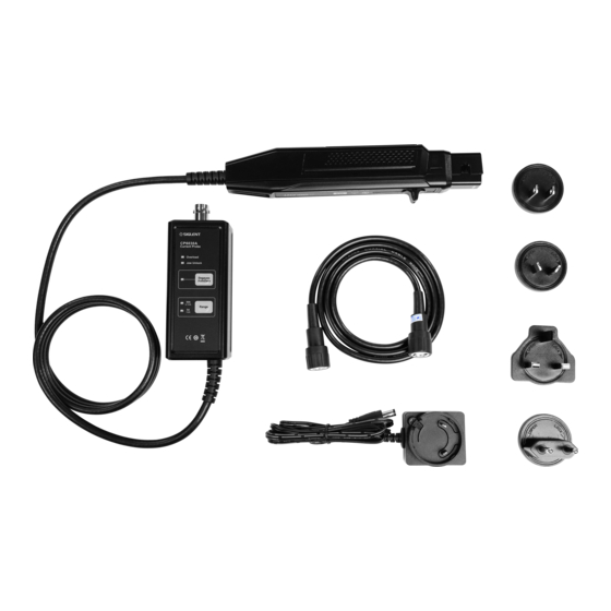
Page 21: Packing List
CP6000/CP4000 Packing list Packing list ITEM Quantity Probe DC-12V/1A adapter BNC connecting line Instruction manual Guarantee card Test report Current Probe Instructions... -
Page 22: Cp4000 Series Current Probe
CP6000/CP4000 CP4000 Series Current Probe CP4000 Series Summary Continuous Maximum Model Peak Current BW(-3dB) Range switch Input Range 100mV/A CP4070A 200A 70Arms 300kHz 10mV /A 50mV/A CP4070 200A 70Arms 300kHz 5mV /A 500mV/A CP4050 140A 50Arms 1MHz 50mV /A 50mV/A CP4020 20Arms 200kHz... -
Page 23: Safety Terms And Symbols
CP6000/CP4000 Avoid Exposed Circuitry. Do not touch exposed connections and components when power is present. Do Not Operate With Suspected Failures. If you suspect there is damage to this product , have it inspected by qualified service personnel. ... -
Page 24: Getting Started
CP6000/CP4000 Getting Started The CP4000 series current probe enables a general purpose oscilloscope to display AC and DC current signals up to 100 amps Peak (70A RMS). The current probe can also make AC and DC measurements with a multimeter by using the recommended accessory MT-246(BNC-to- banana) plug adapter. -
Page 25: Basic Operation
CP6000/CP4000 Basic Operation Before using the probe, the batteries or specified power adaptor must be installed. WARNING! Do not clamp the probe onto circuits with voltages greater than 600 VAC. Personal Injury or damage to the probe may result. Always connect the CP4000 current probe output to the instrument before clamping onto the circuit under test. - Page 26 CP6000/CP4000 clear and stable view of the signal. Set the oscilloscope input to DC volts ti see both the AC and DC current; Set the channel to AC to see the AC current only. The current drawn by different devices look much different than that of others. While the RMS current can only be used in low frequency current, the momentary peaks may be quite high.
-
Page 27: Specifications
CP6000/CP4000 Specifications Model CP4020 CP4050 CP4070 CP4070A BW(-3dB) DC-200kHz DC-1MHz DC-300kHz DC-300kHz ≤1.75uS ≤0.35uS ≤1.2uS ≤1.2uS Rise time Continuous maximum 20Arms 50Arms 70Arms 70Arms input range Max peak 140A 200A 200A current value 50mV/A 500mV/A 50mV/A 100mV/A Range switch 5mV /A 50mV /A 5mV /A 10mV /A... -
Page 28: Mechanical Specifications
CP6000/CP4000 Mechanical Specifications Model CP4020 CP4070 CP4050 CP4070A Dimensions 231*67*36mm 262*81*36mm 280*70*32mm Maximum 10.3mm 10.3mm 11mm Conductor size Cable Length 200cm 100cm 100cm Weight 310g 310g 260g Environmental Characteristics Model CP4020 CP4070 CP4050 CP4070A Operating 0℃~50℃ (+32° F ~ + 122° F) Temperature Nonoperating -20℃~80℃(-20°... - Page 29 CP6000/CP4000 CP4050 CP4070A Maximum current versus frequency Maximum current versus frequency CP4050 CP4070A DC signal linearity in the 50mV/A range DC signal linearity in the 10mV/A range CP4050 CP4070A Phase versus frequency at 1A peak Phase versus frequency at 1A peak Current Probe Instructions...
-
Page 30: Certifications And Compliances
CP6000/CP4000 Certifications and compliances Compliance was demonstrated to the following specification as listed in the Official Journal of the European Union: Low Voltage Directive 73 / 23 / EEC,as amended by 93 / 68 / EEC EN 61010-1/A2:1995 Declaration Safety requirements for electrical equipment for measurement, control, and of Conformity laboratory use. -
Page 31: Care And Maintenance
Do not forcefully pull the input and output lead to prevent bending, twisted and folding. Contact SIGLENT SIGLENT TECHNOLOGIES CO., LTD Address: 3/F, Building 4, Antongda Industrial Zone, Liuxian Road, 68 District, Baoan District, Shenzhen, P.R. CHINA Service Tel: 0086 755 3661-5186 Post Code: 518101 E-mail:sales@siglent.com... - Page 32 DC power supplies, electronic loads and other general purpose test instrumentation. Since its first oscilloscope was launched in 2005, SIGLENT has become the fastest growing manufacturer of digital oscilloscopes. We firmly believe that today SIGLENT is the Headquarters: best value in electronic test & measurement.
Need help?
Do you have a question about the CP6000 Series and is the answer not in the manual?
Questions and answers