
Subscribe to Our Youtube Channel
Related Manuals for SIGLENT SSA3000X-R


Summary of Contents for SIGLENT SSA3000X-R
- Page 1 SSA3000X Plus Spectrum Analyzer SSA3000X-R Real-Time spectrum Analyzer SVA1000X Spectrum & Vector Network Analyzer User Manual UM0703P-E02C User Manual...
- Page 3 ● SIGLENT products are protected by patent law worldwide ● SIGLENT reserves the right to modify or change parts of or all the specifications or pricing policies at company’s sole decision. ● Information in this publication replaces all previously corresponding material.
-
Page 4: Safety Information
SIGLENT Safety Information General Safety Summary Carefully read the following safety precautions to avoid any personal injury or damage to the instrument and any products connected to it. To avoid potential hazards, please use the instrument as specified. Use Proper AC Power Line Only the power cord designed for the instrument and authorized by the local country should be used. -
Page 5: Safety Terms And Symbols
SIGLENT Use proper Fuse. Use Only the Specified Fuse. Keep Product Surfaces Clean and Dry. To avoid the influence of dust and/or moisture in the air, please keep the surface of the device clean and dry. Do Not Operate in Wet Conditions. -
Page 6: Measurement Category
SIGLENT Measurement Category Measurement Categories This analyzer can make measurements in other circuits that are not directly connected to mains. WARNING This analyzer can only be used for measurements within its specified measurement categories. Not to use the product for measurements within other measurement categories, such as CAT II, CAT III, CAT IV. -
Page 7: Working Environment
SIGLENT Working Environment Temperature Operating: 0℃ to +40℃ Non-operation: -20℃ to +70℃ Humidity Under +35℃: ≤80% relative humidity +35℃ to +40℃: ≤60% relative humidity WARNING To avoid short circuit inside the instrument or electric shock, please do not operate in humid environment. -
Page 8: Ventilation Requirement
SIGLENT Ventilation Requirement This analyzer uses fan to force cooling. Please make sure that the air intake and exhaust areas are free from obstructions and have free air. When using the analyzer in a bench-top or rack setting, provide at least 10 cm clearance beside, above and behind the instrument for adequate ventilation. -
Page 9: L'information De Sûreté
SIGLENT L'information de sûreté Résumé général de sûreté Lisez soigneusement les mesures de sécurité suivantes pour éviter n'importe quelles blessures ou les dommages à l'instrument et à tous les produits se sont reliés à eux. Pour éviter des risques, utilisez svp l'instrument comme indiqué. - Page 10 N'importe quel entretien, ajustement ou remplacement particulièrement aux circuits ou aux accessoires doivent être exécuté s par le personnel autorisé par SIGLENT. Ne fonctionnez pas en conditions humides. Afin d'éviter de court-circuiter à l'intérieur du dispositif ou de la décharge é lectrique, svp ne fonctionnez pas dans un environnement humide.
-
Page 11: Limites Et Symboles De Sûreté
SIGLENT Limites et symboles de sûreté Limites en ce manuel. Ces limites peuvent apparaî tre en ce manuel : Les rapports d'avertissement D'AVERTISSEMENT indiquent les conditions ou les pratiques qui pourraient avoir comme conséquence les dommages ou la perte de la ie. -
Page 12: Catégorie De Mesure
SIGLENT Catégorie de mesure Les analyzers peuvent faire des mesures dans d'autres circuits qui ne sont pas directement reliés aux forces. Pour ne pas employer le produit pour des mesures dans d'autres catégories de mesure, telles que le CAT II, CAT III, CAT IV. -
Page 13: Environnement De Fonctionnement
SIGLENT Environnement de fonctionnement Température En fonctionnement: 0 à + 40 Non-fonctionnement: -20 à + 70 Humidité Moins de + 35: humidité relative ≤80% + 35 à + 40 ℃: humidité relative ≤60% EN AVERTISSANT d'éviter le court-circuit à l'intérieur de l'instrument ou de la dé charge électrique, svp ne fonctionnez pas dans l'environnement humide. -
Page 14: Soin Général Et Nettoyage
SIGLENT de l'analyzer dans un mettre hors jeu-dessus ou un arrangement de support, fournissez au moins le dé gagement de 10 centimètres prè s, au-dessus et derrière de l'instrument pour à ventilation proportionnée. La ventilation insatisfaisante peut causer l'augmentation de la température qui endommagerait l'instrument. -
Page 15: Allgemeine Sicherheitshinweise
SIGLENT Allgemeine Sicherheitshinweise Um Verletzungen oder Schäden am Gerä t und den damit verbundenen Produkten zu vermeiden, lesen Sie die folgenden Sicherheitshinweise sorgfältig durch. Um mögliche Gefahren zu vermeiden, verwenden Sie bitte das Gerät wie angegeben. Wartungsarbeiten an diesem Gerät dürfen nur von qualifiziertem Reparaturpersonal durchgeführt werden. -
Page 16: Sicherheitshinweise Und Symbole
SIGLENT Sicherheitshinweise und Symbole In diesem Produkt verwendete Begriffe. Diese Begriffe können im Produkt erscheinen: GEFAHR weist auf eine mögliche, sofortige und direkte Verletzung oder Gefährdung hin. WARNUNG weist auf möglicherweise auftretende Verletzungen oder Gefahren hin VORSICHT weist auf möglicherweise auftretende Schäden am Gerä t oder anderen Gegenständen... -
Page 17: Table Of Contents
SIGLENT CONTENTS COPYRIGHT AND DECLARATION ........................I SAFETY INFORMATION ............................. II ............................II ENERAL AFETY UMMARY ............................ III AFETY ERMS AND YMBOLS ............................IV EASUREMENT ATEGORY ............................V ORKING NVIRONMENT ............................. VI ENTILATION EQUIREMENT ..........................VI ENERAL ARE AND LEANING L'INFORMATION DE SÛRETÉ... - Page 18 SIGLENT ............................15 ASIC ETTINGS 2.1.1 Frequency ............................15 2.1.2 Span ............................... 20 2.1.3 Amplitude ............................22 2.1.4 Auto Tune ............................25 ..........................27 WEEP AND UNCTIONS 2.2.1 BW ..............................27 2.2.2 Trace .............................. 29 2.2.3 Detect ............................31 2.2.4 Sweep ............................
- Page 19 SIGLENT CHAPTER 4 DISTANCE-TO-FAULT MODE ....................80 ............................80 NTERFACE ............................81 EASUREMENT 4.2.1 Start Distance ..........................81 4.2.2 Stop Distance ..........................81 4.2.3 Unit ..............................82 4.2.4 Velocity Factor ..........................82 4.2.5 Cable Atten ............................ 83 4.2.6 Window ............................83 4.2.7...
- Page 20 SIGLENT 7.2.1 Frequency ............................ 114 7.2.2 Span ............................. 115 7.2.3 Amplitude ............................ 116 ..........................119 WEEP AND UNCTIONS 7.3.1 BW ............................... 119 7.3.2 Trace ............................120 7.3.3 Detect ............................121 7.3.4 Sweep ............................121 7.3.5 Limit ............................. 123 ..............................124 ARKER 7.4.1...
- Page 21 SIGLENT 8.3.7 Create Folder ..........................140 8.3.8 Operate ............................140 ............................141 HORTCUT 8.4.1 Preset............................141 8.4.2 Couple ............................151 8.4.3 Help ............................. 152 8.4.4 Save ............................. 152 CHAPTER 9 PROGRAMMING OVERVIEW ....................153 ......................153 EMOTELY PERATING THE NALYZER 9.1.1...
-
Page 22: Chapter 1 Quick Start
The consigner or carrier will be responsible for damages to the instrument resulting from shipment. SIGLENT will not provide free maintenance or replacement. Inspect the instrument If the instrument is found to be damaged, defective or fails in electrical or mechanical tests, please contact SIGLENT. -
Page 23: Preparing For Use
SIGLENT Figure 1-2 Top View 1.3 Preparing for Use 1.3.1 Adjust the Supporting Legs Adjust the supporting legs properly to use them as stands to tilt the analyzer upwards for stable placement as well as easier operation and observation of the instrument display. -
Page 24: Front Panel
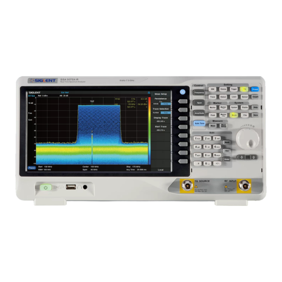
SIGLENT 1.4 Front Panel Figure 1-6 the Front Panel Table 1-1 Front Panel Description Description Description User Graphical Interface, touch support RF Input, VNA port 2 Menu Control Keys TG Output, VNA port 1 Function Keys 3.5 mm Earphone interface... - Page 25 SIGLENT Table 1-2 Function keys description Control Keys Description Frequency Set the parameters of frequency, and Peak→CF, CF→Step. Span Set the parameters of span, and X-scale (Log-Linear) setup. Amplitude Set the parameters of amplitude, including Ref Level, Attenuator, Preamp, etc.; and Correction setup.
-
Page 26: Front Panel Key Backlight
SIGLENT 1.4.2 Front Panel Key Backlight The on/off state and the color of the backlights of some keys at the front panel indicate the working state of the analyzer. The states are as listed below. Power Switch Constant on: indicates the instrument is in normal operating state. -
Page 27: Front Panel Connectors
● The analyzer can serve as a “host” device to connect external USB devices. This interface is available for USB storage devices, the SIGLENT GPIB-USB adapter, wireless or wired mouse and keyboard, or the SIGLENT Ecal electronic calibration module. ●... -
Page 28: Rear Panel
SIGLENT Figure 1-10 Front Panel Connectors (2) TG SOURCE, VNA PORT 1 ● The TG SOURCE can be connected to a device-under-test (DUT) through a cable with a male N- type male connector. ● In the VNA mode, this port is used as the single port of S11 and the output port of S21. - Page 29 SIGLENT Handle Pull up the handle vertically for easy carrying of the instrument. When you do not need the handle, press it down. USB Device Interface Through this interface, the analyzer can be connected to PC for remote control. LAN Interface Through this interface, the analyzer can be connected to your local network (LAN) for remote control.
-
Page 30: User Interface
Figure 1-12 User Interface of spectrum analyzer mode Table 1-3 User Interface labels of spectrum analyzer mode Name Description SIGLENT SIGLENT logo Reference level UNCAL The sweep time is less than the auto couple time, the measure result may have decreased accuracy... - Page 31 SIGLENT identification Main menu touch logo Clicking this button will bring up the main menu Menu title Function of the current menu. Menu items Menu items of the current function Operation status LOCAL or REMOTE mode. When REMOTE, keys would be locked.
- Page 32 SIGLENT Figure 1-13 User Interface of Vector Network Analyzer Mode Table 1-4 Vector Network Analyzer Mode User Interface labels Name Description SIGLENT SIGLENT logo Calibration Status Cor: Calibrated; Off : Correction Off; C?: Need to re-calibrate; Port Extensions P: Port Extensions is On...
-
Page 33: Mode
SIGLENT 1.7 Mode The analyzer offers a variety of operating modes that can be purchased separately. They can be selected via the Mode key: ● Spectrum Analyzer Mode The default mode of the analyzer. It offers a general-purpose spectrum analyzer with a tracking generator, and some advanced measurement. -
Page 34: Firmware Operation
1.8.3 Firmware Upgrade Follow this procedure to update the instrument firmware: Download the firmware package from an official SIGLENT website. Extract and copy the .ADS file into the root directory of an USB stick. Plug the USB stick into the USB Host connector. Press System-> “System Info”-> “Firmware Update”;... -
Page 35: Touch Operation
SIGLENT You can also remote monitor and control the analyzer in Web Browser or Easy Spectrum. For more details, refer to the ‘Programming Guide’ or contact your nearest SIGLENT office. 1.10 Touch Operation The analyzer has a 10.1-inch multi-touch screen and supports various gesture operations. Including: ●... -
Page 36: Chapter 2 Spectrum Analyzer Mode
SIGLENT Chapter 2 Spectrum Analyzer Mode Press Mode, select ‘Spectrum Analyzer’ to enter spectrum analyzer mode. The ‘Spectrum Analyzer’ mode is the default mode of the analyzer. In this mode, the Mode backlight does not light up; in other modes, the Mode backlight will light up. - Page 37 SIGLENT Related to Start Freq, Stop Freq Start Frequency 2.1.1.2 Set the start frequency of the current sweep. The start and stop frequencies are displayed at the bottom of the grid respectively. ● The span and center frequency vary with the start frequency when the Span does not reach the minimum.
- Page 38 SIGLENT Freq Offset 2.1.1.4 Set the frequency offset value to illustrate the frequency conversion between the measured device and the input of the spectrum analyzer. ● This parameter does not affect any hardware settings of the spectrum analyzer, but only changes the display values of center frequency, start frequency and stop frequency.
- Page 39 SIGLENT signal, the change of the measured signal can be tracked and measured all the time. The signal tracking process is shown in the following figure: Figure 2-1 Signal Tracking Flow ● When Marker1 is on, turn on signal tracking, a point whose amplitude does not change more than 3 dB near Marker1 will be searched and marked, and the frequency at that point will be set to center frequency.
- Page 40 SIGLENT Figure 2-2 before Peak -> CF Figure 2-3 after Peak -> CF CF -> Step 2.1.1.8 Set the current center frequency as the Freq Step. At this point, the Freq Step will switch to “Manual”...
-
Page 41: Span
SIGLENT mode automatically. This function is usually used in channel switching. For example, in harmonic measurement, firstly locate the signal at the center frequency (CF) of the display, and then execute CF->Step. Next you can press the upward direction key continuously to measure each order of harmonic in sequence. - Page 42 SIGLENT • SPAN: Zoom In and Zoom Out; • Sweep: Sweep Mode; Marker->: M->CF, M->CF step, M->Start Freq, M->Stop Freq, △M->Span and △M->CF; • Marker Fn: Read Out (default option: △Time); • Zoom In 2.1.2.4 Set the span to half of its current value. At this point, the signal on the screen will be amplified to observe signal details.
-
Page 43: Amplitude
SIGLENT 2.1.3 Amplitude Set the amplitude parameters of the analyzer. Through modifying these parameters, signals under measurement can be displayed in a proper mode for easier observation and minimum error. Any change of Ref Level, Attenuator Value, Preamp mode and Ref Offset will restart sweep. - Page 44 SIGLENT Table 2-8 Attenuator Parameter Explanation Default 20 dB Range 0 ~ 31 dB Unit Knob Step 1 dB Direction Key Step 5 dB Related to Preamp, Ref level Note: the maximum attenuator value of different machine models may be different, please refer to the data manual specifically.
- Page 45 SIGLENT Scale 2.1.3.5 Set the logarithmic units per vertical grid division on the display. This function is only available when the scale type is set to “log”. ● By changing the scale, the displayed amplitude range is adjusted. ● The Minimum range: Reference level –10 × current scale value.
-
Page 46: Auto Tune
SIGLENT Range -100 dB ~ 100 dB Unit Knob Step Not support Direction Key Step Not support Related to Ref Level Correction 2.1.3.8 Correct the displayed amplitude to compensate for gains or losses from external devices such as antennas and cables. When using this function, you can view the correction data table and save or load the current correction data. - Page 47 SIGLENT search is finished. ● Some parameters such as the reference level, scale, input attenuation and maximum mixing level may be changed during the auto search. Figure 2-5 before Auto Tune Figure 2-6 after Auto Tune User Manual...
-
Page 48: Sweep And Functions
SIGLENT 2.2 Sweep and Functions 2.2.1 BW The bandwidth menu contains the RBW (Resolution Bandwidth), VBW (Video Bandwidth), average type and filter type. Filter type includes the EMI filter type that enables EMI measurement controls. Resolution Bandwidth 2.2.1.1 Set the resolution bandwidth in order to distinguish between signals which have frequency components that are near one another. - Page 49 SIGLENT Table 2-13 VBW Parameter Explanation Default 1 MHz Range 1 Hz ~ 1 MHz Unit MHz, kHz, Hz Knob Step in 1, 3 sequence Direction Key Step in 1, 3 sequence Relation RBW, V/R Ratio, Sweep Time V/R Ratio 2.2.1.3...
-
Page 50: Trace
SIGLENT signal. This scale is suitable for observing rise and fall behavior of AM or pulse-modulated signals such as radar and TDMA transmitters. Filter 2.2.1.5 Set the RBW filter type. The analyzer supports two kinds of RBW filters: “Gauss” (-3 dB bandwidth) and “EMI”... - Page 51 SIGLENT Clear Write Erases any data previously stored in the selected trace, and display the data sampled in real-time of each point on the trace. Max Hold Retain the maximum level for each point of the selected trace. Update the data if a new maximum level is detected in successive sweeps.
-
Page 52: Detect
SIGLENT Input X, Y Input X, Y can be applied to trace A, B, C, or D. Calculation Type The analyzer provides the calculation types as shown below: ● Power Diff: X-Y+Offset→Z ● Power Sum: X+Y+Offset→Z ● Log Offset: X+ Offset→Z ●... -
Page 53: Sweep
SIGLENT of the corresponding time interval. This detector type is applicable to noise or noise-like signal. Normal Normal detector (also called ROSENFELL Detector) displays the maximum value and the minimum value of the sample data segment in turn: Odd-numbered data points display the maximum value and even-numbered data points display the minimum value. - Page 54 SIGLENT Sweep Rule 2.2.4.2 The analyzer provides two sweep time rules to meet the different sweep time requirements: ● Speed: Activates the default fast sweep time rule. ● Accuracy: Activates the normal sweep time rule to ensure increased measurement accuracy.
-
Page 55: Trigger
SIGLENT Sweep Mode 2.2.4.4 Sweep mode includes auto mode, sweep mode and FFT mode. 1. Auto When the sweep mode is auto, the analyzer selects the sweep mode automatically between Sweep and FFT Mode in the shortest time. 2. Sweep True swept operation including point-by-point scanning. -
Page 56: Limit
SIGLENT Video Trigger 2.2.5.2 A trigger signal will be generated when the system detects a video signal of which the voltage exceeds the specified video trigger level. Set the trigger level with the video trigger menu entry. At this point, the trigger level line (Trig Line) and value are displayed on the screen. - Page 57 SIGLENT Del Point Delete the point whose number is selected in Mode. Del All Delete all the points. Save/Load Save or load the limit file. X Offset Set offsets of X axis. Y Offset Set offsets of Y axis Limit2 2.2.6.3...
-
Page 58: Tg (Tracking Generator)
SIGLENT Note that all the points of the current limit line will be deleted if the X-axis unit changes. 2.2.7 TG (Tracking Generator) Set the parameters related to the tracking generator (TG) and normalize. 2.2.7.1 The tracking generator is a signal source with an adjustable frequency and amplitude. When the TG is enabled, a signal with the same frequency of the current sweep signal will be output from the [TG SOURCE] connector at the front panel. - Page 59 SIGLENT Normalize 2.2.7.4 Normalization can eliminate errors in the TG Level. Before using this function, connect the [TG SOURCE] output terminal of the TG with the [RF INPUT] input terminal of the analyzer. The reference trace can be stored by pressing the “Store Ref” button after the current sweep finished.
-
Page 60: Demod
SIGLENT This operation differs from the Ref Level function in the AMPT menu. This parameter has no influence on the reference level of the analyzer. Table 2-25 Reference level under normalization Parameter Explanation Default 0 dB Range -200 dB ~ 200 dB... - Page 61 SIGLENT modulated signal. More demodulation analysis, please refer to AM/FM modulation analyzer in MA option. Earphone 2.2.8.2 Set the status of the earphone. When it is on, the demodulated signal can be heard through the earphone during the demodulation. By default, it is off.
-
Page 62: Marker
SIGLENT 2.3 Marker 2.3.1 Marker The marker appears as a rhombic sign (as shown below) for identifying points on a trace. You can easily read the amplitude, frequency and sweep time of the marked point on the trace. Figure 2-9 Marker ●... - Page 63 SIGLENT Table 2-29 Marker parameters Parameter Explanation Default Center Frequency Range 0 ~ Full Span Unit Readout = Frequency: GHz, MHz, kHz, Hz Readout = Time or Period: s, ms, us, ns, ps Knob Step Readout = Frequency, Step = Span/(Sweep Points - 1)
- Page 64 SIGLENT Fixed 2.3.1.5 One of the marker types. When “Fixed” is selected, the X-axis and Y-axis of the marker will not change by the trace and can only be changed through the menu. The fixed marker is marked with "+".
-
Page 65: Marker
SIGLENT 2.3.2 Marker -> M->CF Set the center frequency of the analyzer to the frequency of the current marker. ● If the Normal marker is selected, the center frequency will be set to the frequency of the current marker. ●... -
Page 66: Marker Fn
SIGLENT ● The function is invalid in Zero span. ΔM->CF Set the center frequency of the analyzer to the frequency difference between the two markers in Delta marker type. ● If the Normal marker is selected, this function is invalid. - Page 67 SIGLENT Figure 2-11 N dB BW When the measurement starts, the analyzer will search for the two points which are located at both sides of the current point with N dB fall or rise in amplitude and display the frequency difference between the two points in the active function area.
-
Page 68: Peak
SIGLENT Knob Step 0.1 dB Direction Key Step 1 dB Freq Counter 2.3.3.4 Turn on or off the frequency counter. The frequency readout is accuracy is up to 0.01 Hz. ● The function is valid only when selecting marker 1. - Page 69 SIGLENT Peak -> CF 2.3.4.1 Execute peak search and set the center frequency of the analyzer to the frequency of the peak. Next Peak 2.3.4.2 Search for and mark the peak whose amplitude is closest to that of the current peak and which meets the peak search condition.
- Page 70 SIGLENT Table 2-31 Peak Threshold Parameter Explanation Default -140 dBm Range -200 dBm ~ 200 dBm Unit Knob Step 1 dB Direction Key Step 5 dB Peak Excursion Set the excursion between the peak and the minimum amplitude on both sides of it. Peaks whose excursions are beyond the specified excursion are treated as real peaks.
-
Page 71: Measurement
SIGLENT 2.4 Measurement 2.4.1 Meas Provide optional measurement functions. When activated, the screen will be divided into two parts. The above part is the measure screen which displays traces, and the other part is used to display measurement results. Reflection 2.4.1.1... -
Page 72: Meas Setup
SIGLENT Spectrum Monitor 2.4.1.7 Display the power of the swept spectrum as an intensity color map commonly referred to as a waterfall chart. Select Spectrum Monitor and press Meas Setup to set the corresponding parameters. 2.4.1.8 Measure the power of the carrier and noise of the specified bandwidth and their ratio. Select CNR and press Meas Setup to set the corresponding parameters. - Page 73 SIGLENT 1. Reset Clear calibration data 2. Calibration In the ssa3000x plus series spectrometer, an external bridge is used for reflection measurement. The connection between the bridge and the spectrometer is shown in the figure below. Figure 2-14 external bridge...
- Page 74 SIGLENT Restart the measurement Channel Power 2.4.2.2 Figure 2-15 Channel Power Measurement Results: Channel power and power spectral density. ● Channel Power: Power within the integration bandwidth. ● Power Spectral Density: Power (in dBm/Hz) normalized to 1Hz within the integration bandwidth.
- Page 75 SIGLENT Span Set the frequency range of the channel. This span which is the same with the span of the analyzer is the frequency range of the sweep. Modifying this parameter will change the span of the analyzer. The channel power span is related to the integration bandwidth.
- Page 76 SIGLENT Measurement parameter: Center frequency, main channel bandwidth, adjacent channel bandwidth and channel spacing Center Freq Set the center frequency. The center frequency is the same with the center frequency of the analyzer display. Modifying this parameter will change the center frequency of the analyzer.
- Page 77 SIGLENT Knob Step Adj Chn space /10, the minimum is 1 Hz Direction Key Step In 1-1.5-2-3-5-7.5 Sequence 2.4.2.4 Figure 2-17 OBW Measurement Results: occupied bandwidth and transmit frequency error. ● Occupied Bandwidth: Integrates the power within the whole span and then calculates the bandwidth occupied by the power according to the specified power ratio.
- Page 78 SIGLENT ● T-Power: The power of the signal from the start line to the stop line. Measurement Parameter: Center frequency, start line, stop line. Center Frequency Set the center frequency, this center frequency which is the same with the center frequency of the analyzer.
- Page 79 SIGLENT 2.4.2.6 Figure 2-19 TOI TOI is an automatic measurement. There are no user controlled parameters. Spectrum Monitor 2.4.2.7 Figure 2-20 Spectrum Monitor Display the power of spectrum of successive scans as a color map. Also call a waterfall chart.
- Page 80 SIGLENT Restart: clear the measurement and then restart it. 2.4.2.8 Figure 2-21 CNR Measurement Results: C/N, Carrier Power, Noise Power. ● C/N: the ratio of Carrier Power to Noise Power. ● Carrier Power: the total power of the carrier bandwidth.
- Page 81 SIGLENT Table 2-42 Noise BW Parameter Explanation Default 3 MHz Range 100 Hz ~ (2*span - 2*|Freq Offset| - Carrier BW) Unit GHz, MHz, kHz, Hz Knob Step Noise BW /10, the minimum is 1 Hz Direction Key Step In 1-1.5-2-3-5-7.5 Sequence 3.
- Page 82 SIGLENT Fundamental Set the frequency of the fundamental wave. If the automatic mode is turned on, the fundamental wave will be automatically found from the first scan. If the automatic mode is turned off, the user can input the fundamental frequency manually.
-
Page 83: Chapter 3 Vector Network Analyzer
Network Analyzer Mode. 3.1 User Interface Figure 3–1 Vector Network Analyzer User Interface Table 3–1 Vector Network Analyzer User Interface Name Description SIGLENT SIGLENT logo C/C!/C?/--- Calibration status Port Extensions indication Marker active Active Marker indication Marker Current trace active marker... -
Page 84: Basic Settings
SIGLENT Points Measurement points number Start frequency The first frequency of a sweep Mode Mode indication Trace active Highlight active trace indication Trace format Unit depend on trace format Trace scale Unit depend on trace format Trace division Unit depend on trace format... -
Page 85: Span
SIGLENT Knob Step Span/200, min 1 Hz Direction Key Step Span/10, min 1 Hz Related to Center Freq, Stop Freq Stop Freq 3.2.1.3 Set the start frequency of the current sweep. The start and stop frequencies are displayed at the bottom of the grid respectively. -
Page 86: Amplitude
SIGLENT Related to Start Freq, Center Freq, Stop Freq Full Span 3.2.2.2 Set the span of the analyzer to the maximum available frequency span. Last Span 3.2.2.3 Set the span to the previous span setting. 3.2.3 Amplitude Set the amplitude parameters of the analyzer. Through modifying these parameters, signals under measurement can be displayed in a proper mode for easier observation and minimum error. -
Page 87: Sweep And Functions
SIGLENT Ref Level 3.2.3.4 Set the reference level to indicate the minimum value that the current grid can display. This value is also displayed in the left status bar of the screen. Table 3-7 Ref Level Parameter Explanation Default 0 dB... -
Page 88: Trace
SIGLENT 3.3.2 Trace Select Trace 3.3.2.1 Select the trace in order to set the corresponding trace parameters. You can also select the trace by clicking on the trace mark displayed in the left status bar of the screen. By default, track 1 is selected and opened. - Page 89 SIGLENT Figure 3-2 data trace & memory trace Trace Hold 3.3.2.5 1. Max Retain the maximum level for each point of the selected trace. Update the data if a new maximum level is detected in successive sweeps. 2. Min Display the minimum value from multiple sweeps for each point of the trace and update the data if a new minimum is generated in successive sweeps.
-
Page 90: Sweep
SIGLENT 2. Data*Mem Multiply the measured data by a memory trace. 3. Data-Mem Subtract a memory trace from the measured data. This function can be used, for example, to subtract a vector error that has been measured and stored (e.g., directivity) from data subsequently measured on a device. -
Page 91: Marker
SIGLENT ● To obtain higher measurement accuracy after calibration, perform calibration using the same number of points as in actual measurements. Table 3-10 Points Parameter Explanation Default Range 101 ~ 751 Unit Knob Step Direction Key Step Sweep 3.3.3.2 Set the sweep mode in single or continuous, the default is continuous. - Page 92 SIGLENT Select Trace 3.4.1.1 The same function as in Trace -> “Select Trace”, please refer to section 3.3.2.1. Select Marker 3.4.1.2 Select one of the four markers. The default is Marker1. When a marker is selected, you can set its type, trace to be marked and other related parameters.
- Page 93 SIGLENT Discrete 3.4.1.6 Turning on discrete mode, a marker moves only between actual measurement points. When a specific marker stimulus value is specified as a numerical value, the marker is placed at the measurement point closest to the specified value. A marker placed between the interpolated points with the discrete mode off automatically moves to the nearest measurement point when the discrete mode is turned on.
-
Page 94: Peak
SIGLENT Figure 3-5 Marker Couple is OFF All Off 3.4.1.8 Turn off all the markers of all traces. 3.4.2 .Peak Select Trace 3.4.2.1 The same function as in Trace -> “Select Trace”, please refer to section 3.3.2.1. Select Marker 3.4.2.2 The same function as in Marker ->... -
Page 95: Marker Fn
SIGLENT Valley->CF 3.4.2.6 Execute valley search and set the center frequency of the analyzer to the frequency of the valley. Cont Peak 3.4.2.7 Turn on or off continuous peak search, which is off by default. When continuous valley search is turned on, the spectrum analyzer performs peak search once after each scan. -
Page 96: Meas
SIGLENT 3.5.2 Meas Select S11 or S21 as the current measurement item. This value is also displayed in the status bar on the left side of the screen. 3.5.3 Format Set the display type of measurement result, enter “Format” submenu, and select the corresponding display type. -
Page 97: Scale
SIGLENT Polar In the polar format, traces are drawn by expressing the magnitude as a displacement from the origin (linear) and phase in an angle counterclockwise from the positive X-axis. This data format does not have a stimulus axis, so frequencies must be read by using the marker. The polar format allows users to select one of the following three data groups for displaying the marker response values. - Page 98 This function is only available when the measurement item is S21. Enter the normalized submenu to make the appropriate selection. Ecal 3.5.6.3 Use the optional SIGLENT electronic calibration kit for calibration. Calibration data is saved as user calibration data. Cal Kit 3.5.6.4 Specify the calibration kit used for mechanical calibration.
- Page 99 SIGLENT to change the standard class definition of the calibration kit depending on the standard you actually use. Port Extensions 3.5.6.5 When extending the calibrated plane to other planes (i.e. port extension) instead of the standard calibration process, the port extension function can be used to compensate for the delay (phase shift) caused by fixtures and other possible losses.
- Page 100 SIGLENT Default 0.66 Range 0.1 ~ 1 Unit Knob Step 0.01 Direction Key Step In 1-2-5 sequence...
-
Page 101: Chapter 4 Distance-To-Fault Mode
This chapter introduces in detail the function keys and menu functions of the front panel under the Distance-To-Fault Mode. 4.1 User Interface Figure 4–1 Distance-To-Fault Mode User Interface Table 4–1 Distance-To-Fault Mode User Interface Name Description SIGLENT SIGLENT logo Cor/C?/-- Calibration status Average times Marker Current trace active marker0 Peak Value Show peak value Menu title Function of the current menu. -
Page 102: Measurement
SIGLENT status Peak Distance The value of the distance corresponding to the peak value Stop Distance End distance of horizontal axis Distance Parameters represented by horizontal axis Marker Table Show marker information Start Distance Startance of horizontal axis Window Show Windwo function type... -
Page 103: Unit
SIGLENT 7.68 × 10 × velocity factor Maximum Distance(meters) = stop freq – start freq (Hz) The wider the span is, the smaller the maximum distance that can be measured. In another words, long distance measurements require small span settings. -
Page 104: Cable Atten
SIGLENT 4.2.5 Cable Atten Set the attenuation factor of the cable-under-test. It is used to compensate the amplitude of peaks in different positions. The DTF calculates the peaks by the final receiving data which has been attenuated by the cable, thus the amplitude of peaks cannot show exactly where the mismatch position is. So the cable atten is used to compensate by length. - Page 105 Calibrating with the specified mechanical calibration requires three loads: open, short, and match. Calibration data is saved as user calibration data. Ecal Use the optional SIGLENT electronic calibration unit for calibration. Calibration data is saved as user calibration data. Cal kit Specify the calibration kit used for mechanical calibration.
-
Page 106: Chapter 5 Modulation Analyzer
SIGLENT Chapter 5 Modulation Analyzer This chapter introduces in detail the function keys and menu functions of the front panel under the Modulation Analyzer Mode. This mode enables modulation analysis of incoming signals. Modulation types are as follows: ● AM analog modulation ●... -
Page 107: Basic Settings
SIGLENT Table 5–1 Modulation Analyzer User Interface Name Description SIGLENT SIGLENT logo Trace Ative trace indication Demod type Display the demodulation type of the current view Data type Display the data type of the current view Marker Current trace active marker... -
Page 108: Measurement
SIGLENT Direction Key Step Freq Step Freq Step 5.2.1.2 Setting the value of Freq Step will change the direction key step and knob step of the center frequency. Table 5-3 Freq Step Parameter Explanation Default 10 kHz Range 1 Hz ~ 100 MHz... - Page 109 SIGLENT Meas Length 5.3.1.4 Set the number of symbols which will be used in calculating the measurement. As the length is longer, the range for statistics is bigger, and the measure time is longer. Table 5-5 Meas Length Parameter Explanation...
- Page 110 SIGLENT Table 5-7 Filter Parameter Parameter Explanation Default 0.35 Range 0 ~ 1 Unit Knob Step 0.01 Direction Key Step 4. Filter Length Set the symbols number of the filter selected. It can be set the same as the transmitter.
- Page 111 SIGLENT Trace 5.3.1.7 The displayed data and format in the measurement windows can be set in Trace menu. 1. Select Trace Select the trace in order to set the corresponding trace parameters. You can also select the trace by clicking on the trace mark displayed in the left status bar of the screen.
-
Page 112: Analog Modulation Analysis
SIGLENT Pi/4 PSK 192 ksps Sqrt Nyquist Nyquist NADC Pi/4 PSK 24.3 ksps Sqrt Nyquist Nyquist 0.35 5.3.2 Analog Modulation Analysis When AM or FM modulation type is selected, analog modulation analysis is carried out. 5.3.2.1 IFBW After entering into the mode AM or FM modulation analysis, set the intermediate frequency bandwidth (IFBW). -
Page 113: Sweep And Functions
SIGLENT Unit kHz、Hz 5.3.2.3 Average Open and close the average option for the measurement result. It can set the average number. When the Avg Number is set to off, the column title "Average" in numerical results view will be changed to "Current". -
Page 114: Chapter 6 Real-Time Spectrum Analyzer
SIGLENT Chapter 6 Real-Time Spectrum Analyzer The model supported by real-time spectrum analysis is SSA3000X-R series. 6.1 Basic Settings 6.1.1 Frequency Set the frequency-related parameters and functions of the analyzer. The sweep will restart when the frequency parameters are modified. - Page 115 SIGLENT Table 6-2 Start Frequency Parameter Explanation Default 0 Hz Range 0 Hz ~ (Full Span -5kHz) Unit GHz, MHz, kHz, Hz Knob Step Step=Span/200 Direction Key Step Center Freq Step Related to Center Freq, Span Stop Frequency 6.1.1.3 Set the stop frequency of the current sweep. The start and stop frequencies are displayed at the lower right sides of the grid respectively.
-
Page 116: Span
SIGLENT Freq Step 6.1.1.5 Setting the value of Freq Step will change the direction key step of center frequency, start frequency, stop frequency and frequency offset. ● At a fixed step change the value of the center frequency can reach the purpose of switching measurement channels rapidly and continuously. -
Page 117: Amplitude
SIGLENT Full Span 6.1.2.2 Set the span of the analyzer to the maximum available frequency span. Zoom In 6.1.2.3 Set the span to half of its current value. At this point, the signal on the screen will be amplified to observe signal details. - Page 118 SIGLENT Unit dBm, dBmV, dBuV, dBuA, V, W Knob Step 1 dBm Direction Key Step 10 dBm Related to Attenuator, Preamp, Ref Offset Note: the maximum reference level of different machine models may be different, please refer to the data manual specifically.
-
Page 119: Sweep And Functions
SIGLENT ● Current signal amplitude range that can be displayed: The Minimum range: Reference level –10 × current scale value. The Maximum range: The reference level. Table 6-9 Scale/Div Parameter Explanation Default 10 dB Range 0.1 dB ~ 20 dB... -
Page 120: Detect
SIGLENT Select Trace 6.2.2.1 The real-time spectrum analyzer allows for up to three traces to be displayed at the same time. Each trace has its own color (Trace A - Yellow, Trace B - Whtie, Trace C - Red). All traces can be set parameter independently. -
Page 121: Sweep
SIGLENT analyzer always captures all the data within a specific time interval and processes (Peak, Average, etc.) the data using the detector currently selected, then it displays the processed data (a single data point) on the screen. Select an appropriate detector type according to the actual application in order to ensure the accuracy of the measurement. - Page 122 SIGLENT Sweep 6.2.4.2 Set the sweep mode in single or continuous, the default is continuous. The corresponding icon of the sweep will be displayed in the status bar at the left of the screen. Single Set the sweep mode to “Single”. You can set the sweep times , and execute the set number of scans every time you press "single time".
-
Page 123: Trigger
SIGLENT Restart 6.2.4.4 Restart will clear all historical data, and restart sweeping to records new data. 6.2.5 Trigger The trigger type can be PvT, frequency template trigger(FMT), Free Run and External. Free Run 6.2.5.1 Trigger conditions are met at any time, which means trigger signals are generated continuously. -
Page 124: Fmt
SIGLENT 1. Trigger Edge Set the trigger edge in external trigger to the rising (Pos) or falling (Neg) edge of the pulse. 2. Trigger Delay Set the trigger delay when external trigger is triggered Table 6-16 Trigger Setup Parameter Explanation... -
Page 125: Marker
SIGLENT 2. Beep A beep is emitted after Out of fmt mask. 3. Stop The waveform stops refreshing after Out of fmt mask 6.3 Marker 6.3.1 Marker The marker appears as a rhombic sign (as shown below) for identifying points on a trace. You can easily read the amplitude, frequency and sweep time of the marked point on the trace. -
Page 126: Peak
SIGLENT ● If no active marker exists currently, a marker will be enabled automatically at the center frequency of the current trace. ● You can use the numeric keys, knob or direction keys to move the marker. The readouts of the marker will be displayed at the upper right corner of the screen. -
Page 127: Marker
SIGLENT Peak->CF 6.3.2.1 Set the current peak frequency to the center frequency. Left Peak 6.3.2.2 Search for and mark the nearest peak which is located at the left side of the current peak and meets the peak search condition. Right Peak 6.3.2.3... -
Page 128: Measurement
SIGLENT ● If the Normal marker is selected, the stop frequency will be set to the frequency of the current marker. ● If the Delta or Delta Pair marker is selected, the stop frequency will be set to the frequency of the Delta Marker. - Page 129 SIGLENT be achieved. Spectrogram 6.4.1.2 Figure 6-2 Spectrogram In the “Spectrogram” display, the same spectral data is shown with a time dimension added to the spectrum display. “Spectrogram” records the relationship between the frequency-domain characteristics of each event and time.
- Page 130 SIGLENT Spectrum + Spectrogram 6.4.1.3 Figure 6-3 Spectrum The top view is spectrum which is shown as amplitude vs. frequency, and the bottom view si spectrogram which is mentioned above. The display trace (D1, D2) specified in the spectrogram is shown as amplitude vs. frequency in the spectrum.
- Page 131 SIGLENT 6.4.1.4 Figure 6-4 PVT In the time domain, after the input data (IQ data) of FFT is detected, the corresponding PvT data can be obtained. The detection period is also the corresponding acquisition time. The Aladdin RTSA supports up to 50000 PVT traces for cyclic storage, and each PvT trace corresponds to a spectrogram trace.
-
Page 132: Meas Setup
SIGLENT amplitude as axes. It can visually observe the relationship between frequency characteristics of events and time, and the temperature of its color represents the magnitude. 6.4.2 Meas setup Open the parameter setting menu corresponding to the currently selected measurement window. The menu of this key only displays the setting items related to the current measurement function. -
Page 133: Chapter 7 Emi Measurement
SIGLENT Chapter 7 EMI Measurement 7.1 Introduction Press Mode, select ‘Emi Measurement’ to enter EMI measurement mode. The user interface for EMI Measurement mode has three display regions showing information regarding different setting menus as shown in the figure below. - Page 134 SIGLENT Next, the measurement searches for the peak signal to build a list of peaks called a “signal list”. The search is based on the defined peak excursion and peak threshold under menu Search. A cross mark is added onto the trace for each peak signal found.
-
Page 135: Basic Settings
SIGLENT 7.2 Basic Settings 7.2.1 Frequency Set the frequency-related parameters and functions of the analyzer. Any change of this parameter will stop the running sequence. Freq(Meter) 7.2.1.1 Set the frequency of the meter measurement. The meter frequency value is displayed at the bottom of the meter window. - Page 136 SIGLENT Start Frequency 7.2.1.3 Set the start frequency of scan. The start and stop frequencies are displayed at the bottom of the grid respectively. ● The span and center frequency vary with the start frequency when the Span does not reach the minimum.
- Page 137 SIGLENT span is set to the maximum, the analyzer enters full span mode. ● Modifying the span may cause an automatic change in RBW if they are in Auto mode. Table 7-5 Span Parameter Explanation Default 270 MHz Range 30 MHz ~ 270 MHz...
- Page 138 SIGLENT Table 7-6 Ref Level Parameter Explanation Default 0 dBm Range -100 dBm ~ 30 dBm Unit dBm, dBmV, dBuV, dBuA, V, W Knob Step In Log scale mode, step = Scale/10 In Lin scale mode, step = 0.1 dBm...
- Page 139 SIGLENT distinguishing small signals from the noise. The corresponding icon “PA” will appear at the left side of the screen when the preamplifier is turned on. Units 7.2.3.4 Set the unit of the Y-axis to dBm, dBmV, dBuV, dBuA, Volts (RMS) or Watts. Default is dBm.
- Page 140 SIGLENT of 0%. ● In Log scale type, the Y-axis denotes the logarithmic coordinate. The value shown at the top of the grid is the reference level and each grid represent the scale value. The unit of Y-axis will automatically switch to the default unit (dBm) in Log scale type when the scale type is changed from Lin to Log.
- Page 141 SIGLENT Range 200 Hz, 9 kHz, 120 kHz, 1 MHz Unit Hz, kHz, MHz Knob Step Direction Key Step Relation Span, Sweep Points RBW(Meter) 7.3.1.2 Set the RBW of meters measurement. Table 7-11 Meter RBW Parameter Explanation Default 9 kHz...
- Page 142 SIGLENT View Freezes and holds the amplitude data of the selected trace. The trace data is not updated as the analyzer sweeps. Blank Disable the trace display and all measurements of this trace. Average Set the averages times of the selected trace.
- Page 143 SIGLENT Even if the sweep mode is turned to “Continue”, scan measurement will not start to sweep immediately until the button Start on the screen or Start Sequence under menu Meas is pressed. Single Set the sweep mode to “Single”. The number on the parameter icon denotes the current sweep times.
- Page 144 SIGLENT Table 7-15 Sweep Points Parameter Explanation Default 2116 Range 2 ~ 20001 Unit Knob Step Not supported Direction Key Step Not supported Meter Mode 7.3.4.4 Set the sweep mode for scan measurement in single or continuous, the default is continuous.
- Page 145 SIGLENT Margin 7.3.5.3 Margin value sets a margin for the limit, which will cause a trace to Fail Margin when the trace is between the limit line and the margin line if the margin switches to on. Table 7-17 Margin...
- Page 146 SIGLENT Table 7-18 Marker parameters Parameter Explanation Default Center Frequency Range 0 ~ Full Span Unit GHz, MHz, kHz, Hz Knob Step Step = Span/(Sweep Points - 1) Direction Key Step Step = Span/10 Select Trace 7.4.1.2 Select the trace to be marked by the current marker. Valid selections include A, B, or C.
- Page 147 SIGLENT by the trace and can only be changed through the menu. The fixed marker is marked with "+". After the marker selects “Delta”, the original marker will become the delta measurement marker, and the related marker of the incrementing sequence number will become the reference “fixed” marker 7.4.1.6...
- Page 148 SIGLENT Peak Threshold Assign a minimum for the peak amplitude. Peaks whose amplitudes are greater than the specified peak threshold are treated as real peaks. Table 7-19 Peak Threshold Parameter Explanation Default -140 dBm Range -200 dBm ~ 200 dBm...
- Page 149 SIGLENT Scan, Search & Measure 7.5.1.3 The complete measurement includes scan, peak search and final measurement. After doing peak search, the signal list will be cleared and populated with the new search result. It will do final measurement on all signals in the signal list and update the information of the signal list.
- Page 150 SIGLENT Points 7.5.3.5 This is the same as 7.2.4.3 Sweep Points. 7.5.4 Search A group of menus let you configure for peak search quickly and easily. This is the same as 7.3.3.3 Search Config. 7.5.5 Meas Meas Signal 7.5.5.1 Set the remeasure type, either on a current signal, all signals, or the marked signal in the signal list.
- Page 151 SIGLENT Clear All Mark 7.5.6.5 Unmark all the signals in the signal list Delete Signal 7.5.6.6 Delete the current signal in the signal list. Delete All 7.5.6.7 Delete all signals in the signal list. Delete Marked 7.5.6.8 Delete all marked signals in the signal list.
- Page 152 SIGLENT 7.5.1 Meter A group of menus let you configure for meter measurement quickly and easily Sweep 7.5.1.1 This is the same as 7.2.4.4 Mete Mode. Dwell Time 7.5.1.2 Set the dwell time for meter measurement. All Off 7.5.1.3 Turn off all the meters. It will expand the scan window automatically.
- Page 153 8.1.2.6 Set whether the instrument will start automatically after power-on. Default does not automatically start. 8.1.3 Interface The analyzer supports communications through LAN, USB and the SIGLENT USB-GPIB adapter as standard remote computer control interfaces. 8.1.3.1 Configure the related parameters of the LAN connection by “Static” or “DHCP” method. As a default, the IP config is DHCP.
- Page 154 Figure 8-1 LAN Config GPIB 8.1.3.2 Configure GPIB port number. The analyzer provides a digital interface for use with an optional SIGLENT USB-GPIB module through the front USB port. Web Server 8.1.3.3 Set web page parameters to use VNC. 1. Port The port number can be set to 5900~5999.
- Page 155 SIGLENT 8.1.4 Calibration Auto Cal 8.1.4.1 Set whether to turn on the auto calibration or not and turn off by default. When Auto Cal is turned on, the analyzer will process self-calibration according to the temperature difference. Half an hour after startup, the device will query temperature itself every minute.
- Page 156 SIGLENT Figure 8-3 Load Option Firmware Update 8.1.5.3 Press “Firmware Update” and you will enter the File menu. Then you can select *.ADS file from memory to upgrade firmware. After firmware upgrade, the machine will restart. Figure 8-4 Firmware Update System Message 8.1.5.4...
- Page 157 SIGLENT LCD Test If the keys at the front panel are transparent, when the key is pressed, the corresponding backlight will turn on when testing it. Touch Test Test whether the touch screen has any defects by touching the test button at specific spots on screen.
- Page 158 SIGLENT Figure 8-5 Inverse color Screenshot 8.2.3 Touch Settings You can turn on or off touch screen settings and touch assistance. Touch assistance can be moved to any position on the screen after the touch screen settings are opened. Figure 8-6 Touch assistance 8.2.4 Power Saving...
- Page 159 SIGLENT operation nor button operation for a certain period. The screen backlight will be turned on after a touch screen operation or button operation. 8.2.5 Annotation If turn on the annotation function, you can add annotations on the screen. Figure 8-7 Annotation Typical operation sequence is: ●...
- Page 160 SIGLENT Unit Knob Step Direction Key Step Scale/Div 8.3 File 8.3.1 Browser Browser type including “Dir” and “File”, Dir: When selected, use the knob or direction keys to change the highlighted directory. File: When selected, use the knob or direction keys to switch among files or sub-folders under the current directory.
- Page 161 SIGLENT factors (Cable loss, Amplifier/Antenna gain, etc.). They are saved in ASCII format, which can be read by humans. CAL(Calibration) CAL is the calibration file, which stores the calibration data in VNA mode. CSV (Comma-Separated Variable) CSV files store instrument configuration (scaling, units, etc.) and raw data (amplitude and frequency values) in ASCII format, commonly viewed in spreadsheet programs like Microsoft ®...
- Page 162 SIGLENT Cut the Selected file or folder, and delete the primary one after paste. Copy Copy the Selected file or folder for paste. Paste Paste the file cut or copied before into the current. Delete Delete the selected file or directory.
- Page 163 SIGLENT Ref Level 0 dBm Attenuator Auto, 20 dB Preamp Units Scale/Div 10 dB Scale Type Ref Offset 0 dBm Corrections RF Input 50 Ω Apply Corrections Correction x Correction x data Null Auto, 1MHz Auto, 1MHz VBW/RBW Avg Type...
- Page 164 SIGLENT Output Z Input X Input Y Constant 0 dB Math Type Detect Select Trace Detect Type of Trace A Pos Peak Limit Limit1 Off, Limit Upper, 0 dBm Limit2 Off, Limit Lower, -100 dBm Test Stop Fail to stop...
- Page 165 SIGLENT Measure Meas Type Measure Setup Channel Power Center Freq 750 MHz Integration BW 2 MHz Span 1.5 GHz ACPR Center Freq 750 MHz Main Channel 1 MHz Adjacent Chn 1 MHz Adj Chn Space 3 MHz Occupied BW Method...
- Page 166 SIGLENT Grid Brightness Screenshot Normal Touch Touch Assistant Power Saving Always On Annotation Display Line Off, 0 dBm Table 8-4 Default Preset of Vector Network Analyzer Mode Parameter Default Frequency Center Freq 750.05 MHz Start Freq 100 kHz Stop Freq 1.5 GHz...
- Page 167 SIGLENT Select Trace Select Marker Measure Meas Format Log Mag Calibration Correction System Z0 Velocity Factor 0.66 Port Extensions Extensions Delay Port1 0 ps Length Port1 0 mm Delay Port2 0 ps Length Port2 0 mm Table 8-5 Default Preset of Distance-To-Fault Mode...
- Page 168 SIGLENT Measure Start Distance Stop Distance 30.39 m Unit Meters Velocity Factor 0.66 Cable Atten 0 dBm Window Hamming Calibration Correction Table 8-6 Default Preset of Modulation Analyzer Mode Parameter Default Measure Meas Type Analog Modulation Frequency Center Freq 100 MHz...
- Page 169 SIGLENT Marker Type Normal Relative To Couple Meas Setup IFBQ Auto, 1.2 MHz EqLPF Auto, 200 kHz Average Avg Times Digital Modulation Frequency Center Freq 100 MHz Freq Step 10 kHz Span Span 31.25 kHz Amplitude Attenuator Auto, 20 dB...
- Page 170 SIGLENT Format of Trace C Log Mag Data of Trace D IQ Meas Time Format of Trace D I-Eye Properties Eye Length Symbol Table Marker Select Trace Select Marker Marker Type Normal Relative To Couple Meas Setup Format 16QAM Symbol Rate...
- Page 171 SIGLENT Units dBuV Scale/Div 10 dB Scale Type Ref Offset 0 dB RBW(Scan) Auto, 120 kHz RBW(Meter) Auto, 9 kHz Sweep Scan Mode Continue Number RBW/Step Auto, 1 Sweep Points 2251 Meter Mode Continue Trace Select Trace Trace Type of Trace A...
- Page 172 SIGLENT Sequence Scan Only Scan Dwell Time 1 ms Meas Signal Current Signal Det.1 Switch Det.1 Dwell Time 5 ms Det.1 Limit for Det.2 Switch Det.2 Dwell Time 5 ms Det.2 Limit for Det.3 Switch Det.3 Dwell Time 5 ms Det.3 Limit for...
- Page 173 SIGLENT Mode Couple Some of the basic parameters are allowed to be set up in coupled operation between different modes. If the Center Freq is set to on in one mode, it applies to all other modes that support center freq setting so that you can switch between any of these modes while center freq will be unchanged.
- Page 174 SIGLENT Chapter 9 Programming Overview The analyzer features LAN, USB Device, and GPIB_USB module interfaces. By using a computer with these interfaces, and a suitable programming language (and/or NI-VISA software), users can remotely control the analyzer based on SCPI (Standard Commands for Programmable Instruments) command set, LabView and IVI (Interchangeable Virtual Instrument), to interoperate with other programmable instruments.
- Page 175 Refer to the following steps to finish the connection via USB: Install NI-VISA on your PC for GPIB driver. Connect the analyzer USB Host port to a PC’s GPIB card port, with SIGLENT USB-GPIB adaptor. Switch on the analyzer Figure 9-4 SIGLENT USB-GPIB Adaptor Press button on the front panel System→Interface→GPIB to enter the GPIB number.
- Page 176 SIGLENT 9.2 Build Communication 9.2.1 Build Communication Using VISA NI-VISA includes a Run-Time Engine version and a Full version. The Run-Time Engine version provides NI device drivers such as USB-TMC, VXI, GPIB, etc. The full version includes the Run-Time Engine and a software tool named NI MAX that provides a user interface to control the device.
- Page 177 SIGLENT Figure 9-7 Set the install path, default path is “C:\Program Files\National Instruments\”, you can change it. Click Next, dialog shown as above. Figure 9-8 Click Next twice, in the License Agreement dialog, select the “I accept the above 2 License Agreement(s).”, and click Next, dialog shown as below:...
- Page 178 SIGLENT Figure 9-10 Now the installation is complete, reboot your PC. 9.2.2 Build Communication Using Sockets/Telnet Through the LAN interface, VXI-11, Sockets and Telnet protocols can be used to communicate with the analyzer. VXI-11 is provided in NI-VISA, while Sockets and Telnet are commonly included in PC’s OS initially.
- Page 179 SIGLENT Using USB 9.3.2.1 Run NI MAX software. Click “Device and interface” at the upper left corner of the software; Find the “USBTMC” device symbol Figure 9-11 Click “Open VISA Test Panel” option button, then the following interface will appear.
- Page 180 SIGLENT Figure 9-13 Select Manual Entry of LAN instrument, select Next, and enter the IP address as shown. Click Finish to establish the connection: Figure 9-14 Note: Leave the LAN Device Name BLANK or the connection will fail. Figure 9-15...
- Page 181 Users can control the analyzer remotely by Easy Spectrum. PC software Easy Spectrum is an easy-to- use, PC-Windows-based remote control tool for Siglent’s analyzer. You can download it from Siglent’s website. To connect the analyzer via the USB/LAN port to a PC, you need install the NI VISA first.
- Page 182 SIGLENT For the further description of the software, please refer to the online help embedded in this software. Figure 9-19 9.3.4 Web Control With the embedded web server, the analyzer can be controlled through LAN from a web browser* on PC and mobile terminals, without any extra driver be installed.
- Page 183 10.1 Service Summary SIGLENT warrants that the products that it manufactures and sells will be free from defects in materials and workmanship for a period of three years (accessories for a period of one year) from the date of shipment from an authorized Siglent distributor. If the product proves defective within the respective period, SIGLENT will provide repair or replacement as described in the complete warranty statement.
- Page 184 Check if the Correction is ON in SA or VNA mode. (4) Calibrate the instrument regularly to reduce or avoid errors that might occur over time. If you need a specific calibration after the stated calibration period, contact SIGLENT or get paid service from authorized measurement agencies.
- Page 185 SIGLENT SCA_CSWL (10) Can't set the Scale/Div with linear MRKT_IOFF (11) The marker type is OFF, please open the current marker MRK_NDELT (12) The marker type is not Delta MRKRT_MBST (13) The marker read out type must be set time...
Need help?
Do you have a question about the SSA3000X-R and is the answer not in the manual?
Questions and answers