Table of Contents
Advertisement
Quick Links
Advertisement
Table of Contents

Related Manuals for SIGLENT SSA3021X


Summary of Contents for SIGLENT SSA3021X
- Page 1 SSA3000X Spectrum Analyzer User Manual UM0703X-E03B...
- Page 2 Declaration SIGLENT products are protected by patent law worldwide SIGLENT reserves the right to modify or change parts of or all the specifications or pricing policies at company’s sole decision. Information in this publication replaces all previously corresponding material.
-
Page 3: Safety Information
SIGLENT Safety Information General Safety Summary Carefully read the following safety precautions to avoid any personal injury or damage to the instrument and any products connected to it. To avoid potential hazards, please use the instrument as specified. Use Proper AC Power Line Only the power cord designed for the instrument and authorized by local country should be used. -
Page 4: Safety Terms And Symbols
SIGLENT Do Not Operate Without Covers Do not operate the instrument with covers or panels removed. proper Fuse. Use only the specified fuse. Keep Product Surfaces Clean and Dry. To avoid the influence of dust and/or moisture in the air, please keep the surface of the device clean and dry. -
Page 5: Measurement Category
SIGLENT Symbols on the product. These symbols may appear on the product: Hazardous protective Earth Warning Test Power Switch Voltage Terminal Ground If find such symbols on the product, consult the manual to find out the nature of the potential... -
Page 6: Working Environment
SIGLENT Working Environment Temperature Operating: 0℃ to +50℃ Non-operation:-20℃ to +70℃ Humidity Under +35℃:≤90% relative humidity +35℃ to +40℃: ≤60% relative humidity WARNING To avoid short circuit inside the instrument or electric shock, please do not operate in humid environment. -
Page 7: Ventilation Requirement
SIGLENT Ventilation Requirement This analyzer uses fan to force cooling. Please make sure that the air intake and exhaust areas are free from obstructions and have free air. When using the analyzer in a bench-top or rack setting, provide at least 10 cm clearance beside, above and behind the instrument for adequate ventilation. -
Page 8: L'information De Sûreté
SIGLENT L'information de sûreté Résumé général de sûreté Lisez soigneusement les mesures de sécurité suivantes pour éviter n'importe quelles blessures ou les dommages à l'instrument et à tous les produits se sont relié s à eux. Pour éviter des risques, utilisez svp l'instrument comme indiqué. - Page 9 N'importe quel entretien, ajustement ou remplacement particulièrement aux circuits ou aux accessoires doivent être exécutés par le personnel autorisé par SIGLENT. Ne fonctionnez pas en conditions humides. Afin d'éviter de court-circuiter à l'intérieur du dispositif ou de la décharge é lectrique, svp ne fonctionnez pas dans un environnement humide.
-
Page 10: Limites Et Symboles De Sûreté
SIGLENT Limites et symboles de sûreté Limites en ce manuel. Ces limites peuvent apparaî tre en ce manuel : Les rapports d'avertissement D'AVERTISSEMENT indiquent les conditions ou les pratiques qui pourraient avoir comme conséquence les dommages ou la perte de la ie. -
Page 11: Catégorie De Mesure
SIGLENT Catégorie de mesure Les analyzers peuvent faire des mesures dans d'autres circuits qui ne sont pas directement reliés aux forces. Pour ne pas employer le produit pour des mesures dans d'autres catégories de mesure, telles que le CAT II, CAT III, CAT IV. -
Page 12: Environnement De Fonctionnement
SIGLENT Environnement de fonctionnement Opération de la température : 10℃ au non-fonctionnement de +40℃ : - 20℃ à l'humidité de +70℃ sous +35℃ : humidité relative +35℃ de ≤90% à +40℃ : humidité relative de ≤60% EN AVERTISSANT d'éviter le court-circuit à l'intérieur de l'instrument ou de la dé charge électrique, svp ne fonctionnez pas dans l'environnement humide. -
Page 13: Soin Général Et Nettoyage
SIGLENT au moins le dégagement de 10 centimètres près, au-dessus et derrière de l'instrument pour à ventilation proportionné e. La ventilation insatisfaisante peut causer l'augmentation de la température qui endommagerait l'instrument. Veuillez ainsi la subsistance l'instrument bien aéré lors du fonctionnement et inspectez la prise et éventez régulièrement. -
Page 14: Allgemeine Sicherheitshinweise
SIGLENT Allgemeine Sicherheitshinweise Um Verletzungen oder Schäden am Gerät und den damit verbundenen Produkten zu vermeiden, lesen Sie die folgenden Sicherheitshinweise sorgfältig durch. Um mögliche Gefahren zu vermeiden, verwenden Sie bitte das Gerät wie angegeben. Wartungsarbeiten an diesem Gerät dürfen nur von qualifiziertem Reparaturpersonal durchgeführt werden. -
Page 15: Sicherheitshinweise Und Symbole
SIGLENT Betreiben Sie das Gerät nicht in einer explosiven Atmosphäre. Vermeiden Sie es, dieses Gerät einem Feuer auszusetzen. Sicherheitshinweise und Symbole In diesem Produkt verwendete Begriffe. Diese Begriffe können im Produkt erscheinen: GEFAHR weist auf eine mögliche, sofortige und direkte Verletzung oder Gefährdung hin. -
Page 16: Table Of Contents
SIGLENT Contents Copyright and Declaration ......................II Safety Information ........................III General Safety Summary ....................III Safety Terms and Symbols ....................IV Measurement Category ...................... V Working Environment ......................VI Ventilation Requirement ....................VII General Care and Cleaning ....................VII L'information de sûreté... - Page 17 SIGLENT 2.1.3 Amplitude ....................20 2.1.4 Auto Tune....................23 Sweep and Functions .................... 25 2.2.1 BW ......................25 2.2.2 Trace ......................27 2.2.3 Detect ......................29 2.2.4 Sweep ......................30 2.2.5 Trigger ......................32 2.2.6 Limit ......................33 2.2.7 TG(Tracking Generator) ................ 34 2.2.8...
-
Page 18: Chapter 1 Quick Start
SIGLENT Chapter 1 Quick Start This chapter guides users to quickly get familiar with the appearance, dimensions, front/ rear panel and the user interface, as well as announcements during first use of SSA3000X series spectrum analyzer. Subjects in this chapter: ... -
Page 19: General Inspection
The consigner or carrier will be responsible for damages to the instrument resulting from shipment. SIGLENT will not provide free maintenance or replacement. Inspect the instrument If the instrument is found to be damaged, defective or fails in electrical or mechanical tests, please contact SIGLENT. -
Page 20: Preparing For Use
SIGLENT 1.3 Preparing for Use 1.3.1 Adjust the Supporting Legs Adjust the supporting legs properly to use them as stands to tilt the Spectrum Analyzer upwards for stable placement as well as easier operation and observation of the instrument. Figure 1-3 Before adjusting Figure1-4 After adjusting 1.3.2 Connect to AC Power Supply... -
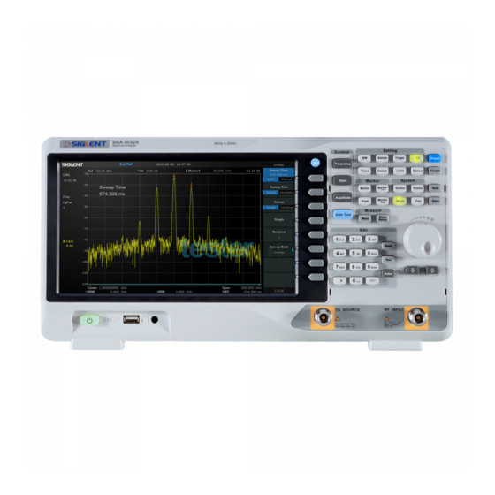
Page 21: The Front Panel
SIGLENT 1.4 The Front Panel Figure 1-6 the Front Panel Table 1-1 Front Panel Description Description Description User Graphical Interface Menu Control Keys Function Keys Knob Arrow Keys RF Input Numeric Keyboard TG Output Earphone interface USB Host Power Switch 1.4.1 Front Panel Function Keys... -
Page 22: Front Panel Key Backlight
SIGLENT Control Keys Description Set the parameters of frequency, and Peak→CF, CF→Step. Frequency Set the parameters of span, and X-scale (Log-Linear) setup. Span Amplitude Set the parameters of amplitude, including Ref Level, Attenuator, Preamp, etc; and Correction setup. Auto Tune Scan the full span rapidly and move the biggest signal to center freq, and automatically sets the optimal parameters according to the signal. -
Page 23: Using The Numeric Keyboard
SIGLENT state of the spectrum analyzer. The states are as listed below. Power Switch Flash on and off alternatively, in breathing state: indicate the unit is in stand-by state. Constant on: indicate the instrument is in normal operating state. -
Page 24: Front Panel Connectors
SIGLENT When the instrument is in remote mode, use this key to return to local mode. Enter In parameter editing, the system will complete the input and insert a default unit for the parameter. 1.4.4 Front Panel Connectors Figure 1-9 Front Panel Connectors Power Switch Power up / Power down the instrument. -
Page 25: Rear Panel
SIGLENT For fear of damaging your hearing, please turn the volume down to zero and gradually turn the volume up after putting on the earphone. TG SOURCE The TG SOURCE can be connected to a receiver through a cable with an N-male connector. - Page 26 SIGLENT USB Device Interface The analyzer can serve as a “slave” device to connect external USB devices. Through this interface, a PC can be connected to control the analyzer remotely through programming or PC software. LAN Interface Through this interface, the analyzer can be connected to your local network for remote control.
-
Page 27: Display Annotations
Figure 1-11 User Interface Table 1-3 User Interface labels Name Description SIGLENT Logo of SIGLENT Reference level UNCAL When the sweep time less than the auto couple time, the measure result may be inaccuracy, then appear “UNCAL” Active function area... -
Page 28: Firmware Operation
SIGLENT means the instrument is upgrading Sweep time Sweep time Span/Stop Frequency The frequency range of the current sweep Sweep progress bar Sweep progress bar Pass/Fail status Pass/Fail status Video bandwidth Spectrum trace Spectrum trace Resolution bandwidth Center/Start frequency The frequency range of the current sweep Trace status Set the trace A\B\C\D parameter. -
Page 29: Enable Option
SIGLENT 1.7.2 Enable Option Refer to the procedures below to activate the options you have purchased. 1, Press System ->“Load Option” 2, Enter the license key in the onscreen window. Press Enter to confirm your input and terminate the license key input. Or 3, Load the .lic file provided by pressing File ->“Load”... -
Page 30: Parameter Setting
SIGLENT Enter Lower Menu (without parameter) Press the corresponding menu key to enter the lower menu. For example, press Calibration to enter the lower menu directly. Direct Execution Press the key to execute the corresponding function. For example, press Peak->CF to execute a peak search and set the center frequency of the analyzer to the frequency of the current peak signal. -
Page 31: Using Built-In Help
SIGLENT 3. Use the arrow keys When the parameter is editable (namely when the parameter is selected), you can increase or decrease the parameter value at the specific step using the direction keys. Press Frequency -> “Center Freq” ... -
Page 32: Chapter 2 Front Panel Operation
SIGLENT Chapter 2 Front Panel Operation This chapter describes in detail the function keys at the front panel and the associated functions. Subjects in this chapter: Basic Settings Sweep and Function Marker Measurement System ... -
Page 33: Basic Settings
SIGLENT 2.1 Basic Settings 2.1.1 Frequency Set the frequency parameters and functions of the analyzer. Restart sweeping every time when the frequency parameters are modified. The frequency range of a channel can be expressed by either of three groups of parameters: Start Frequency, Center Frequency and Stop Frequency. - Page 34 SIGLENT Table 2-2 Start Frequency Parameter Explanation Default 0 GHz Range Zero Span, 0 Hz ~ Full Span Nonzero Span, 0 Hz ~ (Full Span-100Hz) Unit GHz\MHz\kHz\Hz Knob Step Span>0, step=Span/200 Span=0, step=RBW/100 Min 1 Hz Direction Key Step Freq step...
- Page 35 SIGLENT Table 2-4 Frequency step Parameter Explanation Default Full Span/10 Range 1Hz ~ Full Span Unit GHz, MHz, kHz, Hz Knob Step Span>0, Step=Span/200 Span=0, Step=100 min 1 Hz Direction Key Step 1-2-5 sequence step Relation RBW, Span and related parameters 2.1.1.5...
-
Page 36: Span
SIGLENT Figure 2-2 after Peak -> CF 2.1.1.6 CF -> Step Set the current center frequency as the CF step. At this point, the CF step will switch to “Manual” mode automatically. This function is usually used with channel switching. Take harmonic waveform measurement for example: locate a signal at the center frequency of a channel, execute CF->Step and then press the down direction key continuously to measure each order of... - Page 37 SIGLENT VBW mode). Variation in the span, RBW or VBW would cause a change in the sweep time. In non-zero span mode, neither is “Video” trigger nor “1/△ time” readout function valid. Table 2-5 Span Parameter Explanation Default...
-
Page 38: Amplitude
SIGLENT 2.1.2.6 Last Span Set the span to the previous span setting. 2.1.2.7 X-Scale Set the scale type of X-axis to Lin or Log. In Log scale type, the frequency scale of X-axis is displayed in the logarithmic form. If the scale type of X-axis is in the logarithmic type form, the scale type will be switched into Lin when turning on Meas. - Page 39 SIGLENT current reference level automatic adjustment. Open the preamplifier; maximum input attenuation can be set to 51dB. When setting parameters do not meet the above formula, can adjust the reference level. Table 2-7 Attenuator Parameter Explanation Default 20 dB...
- Page 40 SIGLENT when the scale type is set to “log”. In process of using pay attention to the following points: By changing the scale, the amplitude range available is adjusted。 The Minimum range: reference level –10 × current scale value;...
-
Page 41: Auto Tune
SIGLENT 2.1.3.8 Correction Correct the amplitude in order to compensate for the gain or loss from external devices such as Antenna and Cable. When using this function, you can view the correction data table and save or load the current correction data. When amplitude correction is turn on, both the trace and related measurement results will be corrected. - Page 42 SIGLENT Figure 2-3 before Auto Tune Figure 2-4 after Auto Tune SSA3000X User Manual 24...
-
Page 43: Sweep And Functions
SIGLENT 2.2 Sweep and Functions 2.2.1 BW Set the RBW (Resolution Bandwidth), VBW (Video Bandwidth), average type parameters of the analyzer and filter shape. 2.2.1.1 Resolution Bandwidth Set the resolution bandwidth in order to distinguish between signals which are close in frequency. - Page 44 SIGLENT 2.2.1.3 V/R Ratio Set the ratio of VBW to RBW. This value is different while measuring different kinds of signals: Sine signal: use 1 to 3 (for faster sweeps) Pulse signal: use 10 (to reduce the influence on the amplitude of transient signals) ...
-
Page 45: Trace
SIGLENT 2.2.2 Trace The sweep signal is displayed as a trace on the screen. 2.2.2.1 Select Trace Spectrum Analyzer allows for up to four traces to be displayed at the same time. Each trace has its own color (Trace 1 - Yellow, Trace 2 - Purple, Trace 3 - Light blue and Trace 4 - Green). All traces can be set parameter independently. - Page 46 SIGLENT 2. Max Hold Retains the maximum level for each trace point of the selected trace. Updates the data if a new maximum level is detected in successive sweeps. 3. Min Hold Display the minimum from multiple sweeps for each point of the trace and update the data if a new minimum is generated in successive sweeps.
-
Page 47: Detect
SIGLENT 2.2.2.7 Calculation Type Spectrum Analyzer provides the calculation types as shown below: Power : X-Y+Offset Power : X+Y+Offset Log : X+Offset Log : X-Y+Ref 2.2.3 Detect The analyzer displays the sweep signal on the screen in the form of trace. For each trace point, the analyzer always captures all the data within a specific time interval and processes (Peak, Average, etc.) the capture data using the detector currently selected, then display the processed data (one... -
Page 48: Sweep
SIGLENT ruled by CISPR. For single frequency point, the detector detects the peaks within QPD dwell time. The peaks detected are weighted using circuit with specified charge and discharge structures as well as the display time constant specified in the CISPR 16 standards. - Page 49 SIGLENT Set the sweep mode to “Single”. The number on the parameter icon denotes the current sweep number. 2. Numbers Set the number of sweeps for a single sweep. In single sweep mode, the system executes the specified number of sweeps and the number shown on the icon in the status bar at the left of the screen varies with the process of the sweep.
-
Page 50: Trigger
SIGLENT 2.2.4.5 QPD Dwell Time Dwell time is the measurement time at a single frequency. QPD detector gets its weighted envelope response during dwell time. The longer dwell time is, the more sufficiently QPD detector responses to a single frequency, the more accuracy the QPD detector envelope is. -
Page 51: Limit
SIGLENT 2.2.6 Limit The analyzer supports Pass/Fail test function. In this function, the measured curve is compared with the pre-edited curve. If the related rules are met, the result is “Pass”; or else is “Fail”. 2.2.6.1 Limit1 Select enable or disable limit1. -
Page 52: Tg(Tracking Generator
SIGLENT selected the point type. The range from 1 to 100 Add point Add a new point for editing. X-axis Edit the X-axis value (frequency or time) of the current point. If the X-axis unit is frequency and the Ref Freq is enabled, edit the frequency difference between the frequency of the current point and the center frequency. - Page 53 SIGLENT Table 2-21 TG Level Parameter Explanation Default 0 dB Range -20 dBm ~ 0 dBm Unit Knob Step 1 dB Direction Key Step 10 dB 2.2.7.3 TG Level Offset Assign a certain offset to the output power of the TG when gains or losses occur between the TG output and external device in order to display the actual power value.
- Page 54 SIGLENT Default reference plane Normalized reference plane Figure 2-6 Normalization 2.2.7.5 Norm Ref Level Adjust the vertical position of the trace on the screen by adjusting the reference level when normalization is enabled. Different from the Ref Level function in the AMPT menu, this parameter has no influence on the reference level of the analyzer.
-
Page 55: Demod
SIGLENT Direction Key Step 2.2.7.7 Ref Trace Set whether to display the reference trace or not. If “View” is selected, the reference trace saved (Trace D) will be shown in “View” type. Note: When normalization is enabled, the unit of Y-axis is “dB” and will not be influenced by the definition in AMPT->Units. - Page 56 SIGLENT 2.2.8.4 Demod Time Set the time for the analyzer to complete a signal demodulation after each sweep. If Earphone is set to “On”, you will hear the demodulated signal through the earphone during the demodulation. A longer demod dwell time would be better to demodulate audio signal.
-
Page 57: Marker
SIGLENT 2.3 Marker 2.3.1 Marker The marker appears as a rhombic sign (as shown below) for identifying the point on the trace. You can easily read the amplitude, frequency and sweep time of the marked point on the trace. ... - Page 58 SIGLENT Table 2-27 Marker parameters Parameter Explanation Default Center Frequency Range 0 ~ Full Span Unit Readout = Frequency , units available are GHz, MHz, kHz, Hz Readout = Time, units available are s, ms, us, ns, ps Knob Step...
- Page 59 SIGLENT b) Open a “Delta” marker and locate it onto a point. Then, reselect the Delta menu to locate the reference marker onto this point. You can modify the location of the delta point to achieve delta measurement. The application of “Delta” marker...
-
Page 60: Marker
SIGLENT number, marker readout type, X-axis readout and amplitude. Through this table you can view the measurement values of multiple points. The table allows for up to eight markers to be displayed at one time. Figure 2-8 Marker table 2.3.2 Marker ->... -
Page 61: Marker Fn
SIGLENT Set the start frequency of the analyzer to the frequency of the current marker. If Normal marker is selected, the start frequency will be set to the frequency of the current marker. If Delta or Delta Pair marker is selected, the start frequency will be set to the frequency of the Delta Marker. - Page 62 SIGLENT 2.3.3.2 Noise Marker Execute the Noise marker function for the selected marker and read the noise power spectral density. If the current marker is “Off” in the Marker menu, pressing Noise Marker will first set it to Normal type automatically; then measure the average noise level at the marked point and normalize this value to 1 Hz bandwidth.
- Page 63 SIGLENT Default -3 dB Range -100 dB ~ 100 dB Unit Knob Step 0.1 dB Direction Key Step 1 dB 2.3.3.4 Freq Counter Turn on or off the frequency counter. The frequency readout is accuracy is up to 0.01 Hz.
-
Page 64: Peak
SIGLENT The default readout mode in Zero span mode is Δ Time. 2.3.4 Peak Open the peak search setting menu and execute peak search. 2.3.4.1 Peak -> CF Execute peak search and set the center frequency of the analyzer to the frequency of the peak. - Page 65 SIGLENT 2.3.4.8 Search Comfit Define the conditions of peak search for various peak searches. A real peak should meet the requirements of both the “Peak Excursion” and “Peak Threshold”. 1. Peak Threshold Assign a minimum for the peak amplitude. Peaks whose amplitudes are greater than the specified peak threshold are treated as real peaks.
-
Page 66: Measurement
SIGLENT 2.4 Measurement 2.4.1 Meas Provide measurement function, the screen will be divided into two parts, the above part is measure screen, displaying trace, the other part is used to display result of a measurement. 2.4.1.1 Channel Power Measure the power and power density within the specified channel bandwidth. When this function is enabled, the span and resolution bandwidth are automatically adjusted to smaller values. -
Page 67: Meas Setup
SIGLENT 2.4.1.6 Spectrum Monitor Display the power of spectrum in color spectrum. Select Spectrum Monitor and press Meas Setup to set the corresponding parameters. 2.4.1.7 Meas Off Turn off all the Meas function. 2.4.2 Meas setup 2.4.2.1 Channel Power Figure 2-10 Channel Power Measurement Results: channel power and power spectral density. - Page 68 SIGLENT integral within this bandwidth. You can use the numeric keys, knob or direction keys to modify this parameter. Table 2-31 Integration BW Parameter Explanation Default 2 MHz Range 100 Hz ~ Span Unit GHz, MHz, kHz, Hz Knob Step...
- Page 69 SIGLENT 2.4.2.2 ACPR Figure 2-11 ACPR Adjacent Channel Power Measurement: Main CH Power, Left channel power and Right channel power. Main CH Power: display the power within the bandwidth of the main power Left channel power : display the power of left channel and the power difference between the left channel and the main channel (in dBc) ...
- Page 70 SIGLENT Table 2-33 Main channel bandwidth Parameter Explanation Default 2 MHz Range 100 Hz ~ Sweep Span Unit GHz, MHz, kHz, Hz Knob Step Integration BW /100, the minimum is 1 Hz Direction Key Step In 1-1.5-2-3-5-7.5 Sequence Adjacent channel bandwidth Set the frequency width of the adjacent channels.
- Page 71 SIGLENT 2.4.2.3 Figure 2-12 OBW OBW measurement: occupied bandwidth and transmit frequency error. Occupied Bandwidth: integrate the power within the whole span and then calculate the bandwidth occupied by the power according to the specified power ratio. Transmit Frequency Error: difference between the center frequency of the channel and the center frequency of the analyzer.
- Page 72 SIGLENT Measurement Parameter: center frequency, start line, stop line. 1. Center Frequency Sets the center frequency, this center frequency which is the same with the center frequency of the analyzer. Modifying this parameter will change the center frequency of the analyzer.
- Page 73 SIGLENT 2.4.2.5 Figure 2-14 TOI TOI is automatic measurement; do not need to set parameters. 2.4.2.6 Spectrum Monitor Figure 2-15 Spectrum Monitor Display the power of spectrum in color spectrum. Spectrogram: Sets the meas state of spectrum monitor. SSA3000X User Manual 55...
-
Page 74: System
SIGLENT 2.5 System 2.5.1 System Set the system parameters. 2.5.1.1 Language The analyzer supports multi-language menu, Chinese and English build-in help and popup messages. Press this key to select the desired display language. 2.5.1.2 Power On/Preset Power On Set the power on setting to Default, Last or one of user. - Page 75 SIGLENT Config or reset related parameters of LAN. As default, the IP config is DHCP. Figure 2-16 Static IP Config GPIB Config GPIB port number. The analyzer provides a USB-GPIB port on the front board. 2.5.1.4 Calibration Auto Cal When Auto Cal opens, the analyzer will process self-calibration regularly. Within half an hour after power-on, the device executes a self-calibration every 10 minutes.
-
Page 76: Display
SIGLENT Load Option Load license, enter license here to load options. Firmware Update Update firmware from .ADS file in storage. After firmware updated, the analyzer will be reboot. 2.5.1.6 Data and Time Display the data and time On or Off. The system time is displayed in “ymd”, “mdy”, “dmy” format in user interface. -
Page 77: File
SIGLENT Control the display grid brightness. Table 2-39 Grid brightness Parameter Explanation Default Range 0 ~ 100% Unit None Knob Step Direction Key Step Screen Text Open or close the current parameter and its value in the wave area. Screenshot Select the screenshot type to normal and color inverse. - Page 78 SIGLENT 2.5.3.5 Save Save Save file in current directory, the file type is set in " Type". An external U disk has the priority to be written in first. STA(Status) STA files can be used to save and recall the instrument configuration. They are saved in binary format, which is designed to be used by the analyzer, not read by humans.
- Page 79 SIGLENT 2.5.3.7 Operate Open/Load: Open the selected folder or directory, Load the selected file. Select All: Select all the files in current directory Cut: Cut the Selected file or folder, and delete the primary one after paste. Copy: Copy the Selected file or folder for paste.
-
Page 80: Shortcut Key
SIGLENT 2.6 Shortcut Key 2.6.1 Preset Recall the preset setting and restore the analyzer to a specified status. Press System ->Pwr On/Preset ->Preset to select “Def”, “Last” or “User”. Press Preset to load the factory settings listed in the following table (except items marked with “**”) or User-defined settings. - Page 81 SIGLENT Trigger Type Free Run Video Trigger 0 dBm External Trigger Rising TG Level -20 dBm TG Lvl Offset 0 dB Normalize Norm Ref Lvl 0 dB Norm Ref Pos 100% Ref Trace Blank Trace Select Trace Trace Type of Trace A...
- Page 82 SIGLENT Select Marker Marker Fn N dB BW -3 dB Read Out Frequency Peak Cont Peak Peak Table Peak Threshold -160 dBm Peak Excursion 15 dB Peak Type Mode Mode Spec Analyzer Measure Meas Type Measure Setup Channel Power Center Freq 1.6 GHz...
-
Page 83: Couple
SIGLENT Screen Text Screenshot Inverse 2.6.2 Couple Set related parameters according to the coupling relationship. Auto all: Set Related parameters automatically according to the coupling relationship. 1. RBW RBW have couple relationship with span. Please refer to the introduction of the "Resolution Bandwidth". -
Page 84: Chapter 3 Remote Control
SIGLENT Chapter 3 Remote Control SSA3000X Series Spectrum Analyzer support LAN, USB Device, and GPIB--USB Host interfaces. By using these interfaces, in combination with programming languages and/or NI-VISA software, users can remotely control the analyzer based on SCPI (Standard Commands for Programmable Instruments) command set, and interoperate with other programmable instruments. -
Page 85: Connecting The Analyzer Via The Usb Host Port
Refer to the following steps to finish the connection via USB: 1. Install NI-VISA on your PC for GPIB driver. 2. Connect the analyzer USB Host port to a PC’s GPIB card port, with SIGLENT USB-GPIB adaptor. 3. Switch on the analyzer 4. -
Page 86: Build Communication
SIGLENT 3.2 Build Communication 3.2.1 Build Communication Using VISA NI-VISA includes a Run-Time Engine version and a Full version. The Run-Time Engine version provides NI device drivers such as USB-TMC, VXI, GPIB, etc. The full version includes the Run-Time Engine and a software tool named NI MAX that provides a user interface to control the device. - Page 87 SIGLENT Set the install path, default path is “C:\Program Files\National Instruments\”, you can change it. Click Next, dialog shown as above. Click Next twice, in the License Agreement dialog, select the “ I accept the above 2 License Agreement(s).” ,and click Next, dialog shown as below: Click Next to run installation.
-
Page 88: Build Communication Using Sockets/Telnet
SIGLENT Now the installation is complete, reboot your PC. 3.2.2 Build Communication Using Sockets/Telnet Through LAN interface, VXI-11, Sockets and Telnet protocols can be used to communicate with the spectrum analyzer. VXI-11 is provided in NI-VISA, while Sockets and Telnet are commonly included in PC’s OS initially. -
Page 89: Send Scpi Commands Via Ni Max
SIGLENT 3.3.2 Send SCPI Commands via NI MAX Users can control the spectrum analyzer remotely by sending SCPI commands via NI-MAX software. 3.3.2.1 Using USB Run NI MAX software. 1, Click “Device and interface” at the upper left corner of the software;... - Page 90 SIGLENT 3. Select Manual Entry of LAN instrument, select Next, and enter the IP address as shown. Click Finish to establish the connection: NOTE: Leave the LAN Device Name BLANK or the connection will fail. 4. After a brief scan, the connection should be shown under Network Devices:...
-
Page 91: Easyspectrum Software
Users can control the spectrum analyzer remotely by EasySpectrum. PC software EasySpectrum is an easy-to-use, PC-Windows-based remote control tool for Siglent’s spectrum analyzer. You can download it from Siglent’s website. To connect the analyzer via the USB/LAN port to a PC, you need install the NI VISA first. - Page 92 SIGLENT An EMI receiver to perform EMI Pre-compliance test including pre scan, peak search, final scan and report generating. For the further description of the software, please refer to the online help embedded in this software. SSA3000X User Manual 74...
-
Page 93: Chapter 4 Troubleshooting And Service
Chapter 4 Troubleshooting and Service 4.1 Service Summary SIGLENT warrants that the products that it manufactures and sells will be free from defects in materials and workmanship for a period of three years (accessories for a period of one year) from the date of shipment from an authorized Siglent distributor. - Page 94 (4) Calibrate the instrument regularly to reduce or avoid errors that might occur over time. If you need a specific calibration after the stated calibration period, contact SIGLENT or get paid service from authorized measurement agencies.
-
Page 95: Contact Us
SIGLENT 4.3 Contact Us China SIGLENT TECHNOLOGIES CO., LTD. Add: Bldg No.4 & No.5, Antongda Industrial Zone, 3rd Liuxian Road, Bao'an District, Shenzhen, 518101, China. Tel: + 86 755 3661 5186 Fax: + 86 755 3359 1582 Email: sales@siglent.com; Website: http://www.siglent.com/ens/...
Need help?
Do you have a question about the SSA3021X and is the answer not in the manual?
Questions and answers