
Related Manuals for SIGLENT SM06035-E01A


Summary of Contents for SIGLENT SM06035-E01A
-
Page 1: Service Manual
Service Manual SDM3055 Series Digital Mulimeter SM06035-E01A 2016 SIGLENT TECHNOLOGIES CO., LT... -
Page 3: Guaranty And Declaration
Declaration SIGLENT products are protected by patent law in and outside of P.R.C. SIGLENT reserves the right to modify or change parts of or all the specifications or pricing policies at company‟s sole decision. Information in this publication replaces all previously corresponding material. -
Page 4: General Safety Summary
General Safety Summary Review the following safety precautions to avoid personal injuries and prevent damages to this product or any products connected to it. To avoid potential hazards, use this product only as specified. Only qualified personnel should perform service procedures. To Avoid Fire or Personal Injuries Use Proper Power Cord. - Page 5 Do Not Operate With Suspected Failures. If you suspect damage occurs to this instrument, have it inspected by qualified service personnel before further operation. Any maintenance, adjustment or replacement especially to the circuits or accessories should be performed by SIGLENT authorized personnel. Keep Product Surfaces Clean and Dry.
-
Page 6: Table Of Contents
Catalog Guaranty and Declaration ......................I General Safety Summary ......................II General Features and Specifications ..................1 General Features........................1 Specifications .......................... 2 Prepare Information ........................6 Functional checking ....................... 6 Power-on Inspection ...................... 6 Default Setup ........................6 Self Test ........................... 7 Performance Verification ....................... - Page 7 Check the Main Board ......................29 Voltage Checking ......................29 Microprocessor Checking .................... 29 Quick Guide for General Failures ..................30 Maintenance ..........................31 Maintain Summary ....................... 31 Repackaging for Shipment ....................31 Contact SIGLENT ......................... 32 SDM3055 Service Manual V...
-
Page 9: General Features And Specifications
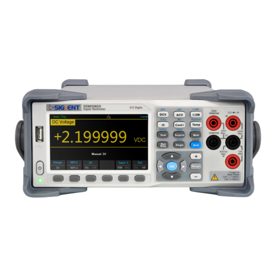
General Features and Specifications SDM3055 is a 5½ dual-display instrument designed with 5½ digits readings resolution and dual-display, especially fitting to the needs of high-precision, multifunction, and automation measurements. It realized a combination of basic measurement functions, multiple math functions, and display functions, etc. -
Page 10: Specifications
Specifications DC Characteristic Accuracy±(% of Reading + % of Range) Temperature Test current or 1 Year coefficient Function Range Load voltage 23℃±5℃ 0℃~18℃ 28℃~50℃ 0.015+ 0.004 0.0015+ 0.0005 200 mV 0.015+ 0.003 0.0010+ 0.0005 0.015+ 0.004 0.0020+ 0.0005 DC Voltage 20 V 200 V 0.015+ 0.003... - Page 11 AC Characteristic Accuracy±(% of Reading + % of Range) Temperature 1Year coefficient Function Range Frequency Range 23℃±5℃ 0℃~18℃ 28℃~50℃ 20 Hz – 45 Hz 1.5 + 0.10 0.01 + 0.005 45 Hz – 20 KHz 0.2 + 0.05 0.01 + 0.005 200 mV 20 KHz –...
- Page 12 Additional wave crest factor error ( not Sine ) Wave crest coefficient Error(% Range) 0.05 Remarks: [1] Specifications are for 0.5 Hour warm-up, “Slow” measurement rate and calibration temperature 18℃~28℃. [2] 20% over range on all ranges except for DCV 1000 V, ACV 750 V, DCI 10 A and ACI 10 A.
- Page 13 2 μA 200 nF 1+0.5 0.02+0.001 2 μF 10 μA 1+0.5 0.02+0.001 200 μF 100 μA 1+0.5 0.02+0.001 10000 μF 1 mA 2+0.5 0.02+0.001 Remarks: [1] Specifications are for 0.5 Hour warm-up and “REF” operation. Using of non-film capacitor may generate additional errors. [2] Specifications are for from 1% to 120% on 2 nF range and ranges from 10% to 120% on other ranges.
-
Page 14: Prepare Information
Prepare Information Before doing performance verifying or procedure adjusting, you should master the following operations to make the mulimeter work in a good state or deal with some simple functional problems. The following contents are included in this chapter: How to perform functional checks ... -
Page 15: Self Test
Default settings Menu or System Option Default setting Range Auto Speed Slow Filter Trg Src Auto Delay Auto Acquire Samples/Trigger VMC Out Statistics Hide Limits Math dB/dBm Ref Value Display Display Number Hold Probe Hold Self Test SDM3055 provides self-test functions, including Key Test, LCD Test, Beeper Test and Chip Test. -
Page 16: Performance Verification
Application Recommended Equipment Zero Offset Verification Keysight 34172B DC Voltage and DC Current Gain Fluke 5522A Verification Siglent SDG2000X SeriesFunction/Arbitrary Frequency Accuracy Verification Waveform Generator AC Voltage and AC Current Fluke 5522A Verification Capacitance Verification Fluke 5522A Performance verification step 1. -
Page 17: Test Considerations
Test Considerations Ensure that the test ambient temperature is stable and between 18°C and 28°C. Ideally the calibration should be performed at 23°C±2°C. Ensure ambient relative humidity is less than 80%. Allow a 30 minute warm–up period with a copper short connected. ... -
Page 18: Dc Voltage And Dc Current Gain Verification
DC Voltage and DC Current Gain Verification Input Error from Nominal Voltage Function Range (1 years) -200mV ±38μV 200mV 200mV ±400μV ±2.3mV -20V DC Volts ±3.8mV -200V 200V ±36mV 200V -500V ±110mV 1000V 1000V ±180mV Input Error from Nominal Current Function Range (1 years) -
Page 19: Frequency Accuracy Verification
Frequency Accuracy Verification Input Error from Nominal (1 years) Vrms Frequency Range 60mV 500kHz 200mV ±50Hz 0.3V 20Hz ±0.2Hz SDM3055 Service Manual 11... -
Page 20: Ac Voltage And Ac Current Verification
AC Voltage and AC Current Verification Input Error from Nominal (1 years) Vrms Frequency Range 1kHz ±500μV 200mV 50kHz 200mV ±2.1mV 100kHz 6.1mV 1kHz ±5 mV 50kHz ±21 mV 100kHz ±61 mV 0.2V 1kHz ±30.4mV 1kHz ±34mV 45Hz ±320mV 20kHz ±50mV 50kHz ±210mV... -
Page 21: Capacitance Verification
Capacitance Verification Input Error from Nominal Capacitance Range (1 years) ±0.08nF 20nF ±0.3nF 20nF 200nF ±3nF 200nF 2μF ±30nF 2μF 20μF ±300nF 20μF 200μF 200μF ±3μF 10000μF 10000μF ±250μF SDM3055 Service Manual 13... -
Page 22: Calibration Adjusting Procedures
The instrument should be calibrated on a regular interval determined by the accuracy requirements of your application. A 1-year interval is adequate for most applications. Accuracy specifications are warranted only if calibration is made at regular calibration intervals. Siglent Technologies never recommends calibration adjustment intervals beyond two years. Calibration is Recommended... -
Page 23: Recommended Test Equipment
2-Wire Ohms Calibration 4-Wire Ohms Calibration Capacitance Calibration Recommended Test Equipment The recommended test equipment for the performance calibration is listed below. If the exact instrument is not available, substitute calibration standards of equivalent accuracy. Recommended Instrument Requirements Model Provide the source of... -
Page 24: Calibration Adjustment Step
Calibration Adjustment step 1. Connect the Calibrator, PC and SDM3055 digital mulimeter as shown below: 2. Open the EasyTest software. 3. Click “open” under the “file” menu, and then select the corresponding Tcl script. 4. Click the “test” button to perform the adjusting procedures. 5. -
Page 25: Assembly Procedures
Assembly Procedures This chapter describes how to remove the major modules from the SDM3055 series generator. To install the removed modules or replace new modules, please follow corresponding operating steps in reverse order. Security Consideration Only qualified personnel should perform the disassembly procedures. Whenever possible, disconnect the power before removing or replacing. -
Page 26: Disassembly Procedures
Disassembly Procedures 1. Turn off the power and remove all measurement leads and other cables, including the power cord, from the instrument before continuing. 2. Rotate the handle to the upright position and remove it by pulling outward where it attaches to the case. 3. - Page 27 4. Remove the screw on the bottom of the instrument and place it in a safe location for re-assembly. Slide off the instrument cover as indicated by the arrow shown below. 5. Remove the cable plug(in the red circle and yellow box shown below) connected to the main body SDM3055 Service Manual 19...
- Page 28 6. Unscrew the 5 captive screws in the rear metal cover and remove the rear metal cover. 7. Unscrew the 4 screws and remove the fan. 8. Remove the cable plug connected to the front pannel. 9. Remove the cable and unscrew all the screws,then you can remove thePCBA.
- Page 29 This concludes the disassembly procedure. To re-assemble the instrument, reverse the procedure. SDM3055 Service Manual 21...
-
Page 30: Troubleshooting
Required Equipments The equipments listed in the table are required to troubleshoot the multimeter. Table 6-1 required equipments Equipment Critical Specifications Example Accuracy ±0.05% Siglent SDM3045X Digital Multimeter 1 mV resolution Oscilloscope 200MHz Bandwidth Siglent SDS2102X 22 SDM3055 Service Manual... -
Page 31: Analog Board Drawing
Analog Board Drawing Analog board is a kind of signal sampling board for output digital signal. It mainly works on signal processing such as AC is converted to DC in order to measure easily magnitude of AC. Please refer to the following drawing to quickly locate the test points on the analog board for easy resolution of the failures you encounter. -
Page 32: Main Board Drawing
Main Board Drawing Main board is used to control and manage the whole internal system of the multimeter. It completes the GUI function, controlling and configuration function for analog board as well as man-machine interaction. Please refer to the following drawing to quickly locate the test points on the main board for easy resolution of the failures you encounter. -
Page 33: Check The Power Supply
Otherwise, it proves to be faulted, please return it to the factory to have it repaired or contact SIGLENT. Note: The main power supply provides an input fuse to protect against the danger of fire in the event of a failure of the power supply circuitry. - Page 34 this fuse will not fail ("open" or "blow") in normal power supply operation except that a significant overload occurs. Replace the entire main power supply assembly if the input fuse fails. 26 SDM3055 Service Manual...
-
Page 35: Check The Analog Board
5-4, it proves to be faulted, please return it to the factory to have it repaired or contact SIGLENT. Table 6-4 Test DC voltages of the analog board Test point... -
Page 36: Analog Board Clock Checking
Analog board Clock Checking Analog board clock is the internal system clock of the multimeter. To verify if the clock on the analog board works normally, please test the clock frequency listed below using an oscilloscope. Table 6-5 Clock Source of the analog Board Test point Name Frequency Stability 1 or 2... -
Page 37: Check The Main Board
SIGLENT Check the Main Board If the main board does need to be removed from the metal shelf located inside the generator, place it on a clean, insulated mat. Testing procedures for the main board are as follows: 1. Several types of connectors are located on the main board. Check if all these are connected properly. -
Page 38: Quick Guide For General Failures
(4) Check the connection between the power supply and the main board. (5) If the instrument still does not work normally, please contact SIGLENT. 2. The instrument starts up with a dark screen: (1) Check the connection between the keypad circuit board and the main board. -
Page 39: Maintenance
In no case shall SIGLENT be liable for indirect, special or consequential damages. Repackaging for Shipment If the unit needs to be shipped to SIGLENT for service or repair, be sure: 1. Attach a tag to the unit identifying the owner and indicating the required service or repair. -
Page 40: Contact Siglent
Contact SIGLENT SIGLENT TECHNOLOGIES CO., LTD Address: 3/F, NO.4 building, Antongda Industrial Zone, 3rd Liuxian Road, 68th District, Baoan District, Shenzhen, P.R. China Tel: 400-878-0807 E-mail: sales@siglent.com http: //www.siglent.com In North America: http://www.siglentamerica.com 32 SDM3055 Service Manual...
Need help?
Do you have a question about the SM06035-E01A and is the answer not in the manual?
Questions and answers