Table of Contents
Advertisement
Quick Links
Step 1:
•
Place the EPIC frame leg with plate facing down on a
protected flat surface.
Step 2:
•
Align holes in the end plate of the cross bar with the
frame. Make sure the tabs on the cross bar are facing
down.
•
Connect cross bar to the frame using 1/4"-20 x 45mm
joint connector bolts and 1/4"-20 joint connector nuts.
•
Use a screw gun and a 4mm hex bit to tighten the
joint connector bolts to the nut. We suggest using
a 4mm hex wrench to hold the nut in place while
tightening the bolt.
•
Repeat for other frame leg.
Step 3:
•
Place the top face down on a protected flat surface so
threaded inserts and pre-drilled pilot holes are facing
up.
Step 4:
•
Place frame leg/cross bar on the top and align with
threaded inserts & pre-drilled pilot holes.
•
Using a screw gun and a 4mm hex bit, secure both
frame legs to top with 1/4"-20 x 15mm joint connector
bolts. Use (8) bolts for each frame leg.
Step 5:
•
Using a screw gun and a # S2 square bit, secure
cross bar to top with #10 x 3/4" square pan screws.
Use one screw per tab with a total of (6) screws being
used (3 per side).
wibenchmfg.com
Specifications are subject to change. Product
images are for illustrative purposes only and may
differ from the actual product.
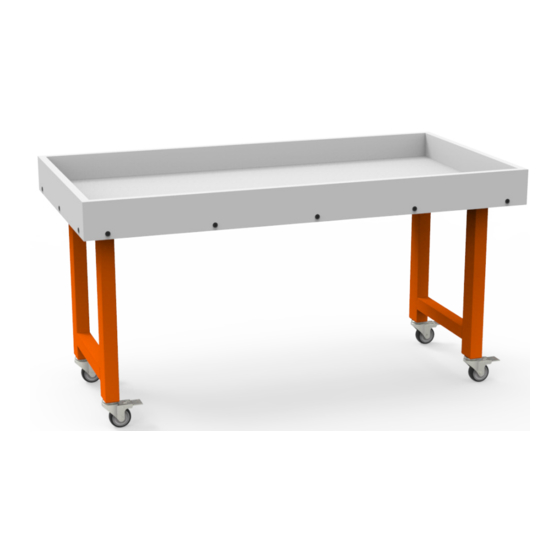
Assembly Instructions
Ingenuity EPIC Table
Before you begin, please make sure all parts and proper
quantities are included. (See Part Identifier Key) Any parts
damaged during shipment must be reported within 24 hours of
receipt. To report information regarding damages or if you have
any questions, please call 800.242.2303.
Step 1
EPIC frame leg
Step 2
Step 3
507 E. Grant St. Thorp, WI 54771 • P - 800.242.2303
To o l s R e q u i r e d
• Screw gun
• # S2 square bit
• 4mm hex bit
• 4mm hex wrench
• 3/4" wrench
Joint connector bolt
Joint connector nut
Cross bar
Tab
Step 5
V032922 Version subject to change
Step 4
1
Advertisement
Table of Contents

Related Manuals for WB Manufacturing Ingenuity EPIC


Summary of Contents for WB Manufacturing Ingenuity EPIC
- Page 1 Assembly Instructions Ingenuity EPIC Table Before you begin, please make sure all parts and proper quantities are included. (See Part Identifier Key) Any parts damaged during shipment must be reported within 24 hours of receipt. To report information regarding damages or if you have any questions, please call 800.242.2303.
- Page 2 Assembly Instructions Ingenuity EPIC Table Step 6: • Before placing caster in the bottom of the frame leg, lock the caster by pushing down on the brake lever. • Twist the stem of the caster into the hole on the bottom of the leg frame.
- Page 3 Assembly Instructions Ingenuity EPIC Table Part Identifier Key Step # Part # Description Qty. Step 2 1/4”-20 x 45mm joint connector bolts 2 per leg frame (4 total) Step 2 04009022 1/4”-20 joint connector nuts 2 per leg frame (4 total)
Need help?
Do you have a question about the Ingenuity EPIC and is the answer not in the manual?
Questions and answers