Table of Contents
Advertisement
Available languages
Available languages
Quick Links
IMPORTANT INSTRUCTIONS - SAVE THESE INSTRUCTIONS
Read all instructions before installing or using the heater. Please adhere to instructions published in
this manual. Failure to do so may be dangerous and may void certain provisions of your warranty.
Heavy Duty Forced Air Unit Heaters
RGX Series
Installation, Operation, & Maintenance Instructions
Model Coding
RGX
Model
Series
Ruffneck™ is a registered trademark of Thermon
Copyright© 2022. All rights reserved.
2 0
3
Kilowatts
Voltage
Contactor
15 - 15 kW
2 - 208
(Optional)
20 - 20 kW
3 - 240
25 - 25 kW
7 - 480
8 - 600
30 - 30 kW
40 - 40 kW
50 - 50 kW
C
T
-
Thermostat
(Optional)
B - Epoxy painted fan blade and motor
L - Energy management controller
V - 120V control voltage (240V is standard)
Part No.MI281.Rev4.02
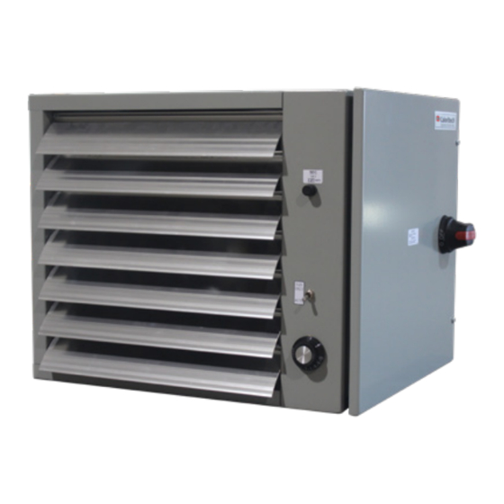
RGX heater with optional thermostat, fan only switch,
disconnect switch and fused control circuit
D
Other Options
D - Disconnect switch
F - Fan only switch
H - HRC main load fuses
K - Fused control circuit
M - Manual reset high limit
N - Low voltage relay (24V)
March 2022
Printed in Canada
®
C
US
Advertisement
Chapters
Table of Contents

Related Manuals for Ruffneck RGX Series


Summary of Contents for Ruffneck RGX Series
- Page 1 50 - 50 kW M - Manual reset high limit N - Low voltage relay (24V) V - 120V control voltage (240V is standard) Ruffneck™ is a registered trademark of Thermon Part No.MI281.Rev4.02 March 2022 Printed in Canada Copyright© 2022. All rights reserved.
-
Page 2: Table Of Contents
TABLE OF CONTENTS A. Important Notices B. Installation B.1 Location ..............................4 B.2 Mounting .............................4 B.3 Electrical ............................... 5 B.4 Sample Wiring Schematics - RGX Series Heater ............. 6 C. Operation C.1 General ..............................10 D. Repair & Replacement D.1 Heating Elements ........................10 D.2 ... -
Page 3: Important Notices
IMPORTANT NOTICES Do not operate heater in wet and humid environments. CAUTION. This symbol indicates a potentially hazardous situation, which, if not avoided, may result Install and maintain clearances as per this manual. in personal injury or damage to the equipment. CAUTION Do not operate the heater in corrosive atmospheres. -
Page 4: Installation
INSTALLATION All applicable codes must be adhered to. For optimum B.2 Mounting performance, the heater should be installed as follows: CAUTION. Install heater no less than 5 inches (127 mm) from walls and 6 inches (152 mm) from ceiling. Mount with B.1 ... -
Page 5: Electrical
Remote Low Voltage Thermostats - The heater can be on the inside of the control cabinet door (or refer to provided with a low voltage control internally wired B.4 Sample Wiring Schematics - RGX Series Heater, for remote connection to 24V thermostats. Ensure page 8. -
Page 6: Sample Wiring Schematics - Rgx Series Heater
Refer to Section B.4 Sample Wiring remote switch leads if this feature is to be available. Schematics - RGX Series Heater, page 6 to 9. Refer to Section B.4 Sample Wiring Schematics - RGX Final Inspection Series Heater, page 6 to 9. - Page 7 B.4 Sample Wiring Schematics - RGX Series Heater (Cont'd) If the wiring schematics in Figure 2 to Figure 7, page 6 to 9, do not match your configuration, check inside the control panel door of the unit for specific wiring schematic. Alternatively, all wiring schematics are available online at www.thermon.com. Figure 3 – 208V and 240V Three Phase with Controls Figure 4 – 208V and 240V Three Phase without Controls...
- Page 8 B.4 Sample Wiring Schematics - RGX Series Heater If the wiring schematics in Figure 2 to Figure 7, page 6 to 9, do not match your configuration, check inside the control panel door of the unit for specific wiring schematic. Alternatively, all wiring schematics are available online at www.thermon. com. CONTINUOUS FAN CONTINUOUS FAN AUTO TH REMOVE THIS JUMPER WHEN CONTINUOUS FAN SWITCH IS USED Figure 5 – 208V and 240V Three Phase with Controls Figure 6 – 240V Single Phase without Controls...
- Page 9 B.4 Sample Wiring Schematics - RGX Series Heater (Cont'd) If the wiring schematics in Figure 2 to Figure 7, page 6 to 9, do not match your configuration, check inside the control panel door of the unit for specific wiring schematic. Alternatively, all wiring schematics are available online at www.thermon. com. CONTINUOUS FAN AUTO TH REMOVE THIS JUMPER WHEN CONTINUOUS FAN SWITCH IS USED Figure 7 – 240V Single Phase with Controls NOTE*: Requires special certification...
-
Page 10: Operation
OPERATION C.1 General To operate heater, ensure power supply is properly Operate the unit for a minimum of 10 minutes to allow the connected as specified in the wiring schematic (refer to heating elements to reach a steady state. If no warm air is Figure 2 to Figure 7, page 6 to 9). discharged from the heater, shut off the unit and refer to Section F. Troubleshooting Tips, page 13. ... -
Page 11: Parts List
PARTS LIST DESCRIPTION E.1 Parts Assembly Diagram & Chart CABINET BOX ASSEMBLY CABINET DOOR ITEM DESCRIPTION SPLITTER BLOCK CONTACTOR CABINET BOX ASSEMBLY TERMINAL BLOCK ELEMENTS CABINET DOOR THERMOSTAT FAN BLADE FUSE CONTACTOR TIME DELAY RELAY HIGH LIMIT ELEMENTS TRANSFORMER DISCHARGE LOUVRE FAN BLADE BAFFLE, CONT. -
Page 12: Parts List
E.2 Parts List Table 3 – Replacement Parts List Refer to E.1 Parts Assembly Diagram & Chart, page 11 for all tables below. Item Description Part Number Item Description Part Number Cabinet box assembly Contact Factory Terminal Block Contact Factory Cabinet Doors 15-50 B11082-01 Thermostat Kit — 15–50 FAT 8A Contactors Contact Factory Time Delay Relay Contact Factory KXF11008-81 15–30... -
Page 13: Troubleshooting Tips
TROUBLESHOOTING TIPS F.1 Heater is not operating F.5 Heater is operating but no heat is present Check all fuses. If equipped with a "CONTINOUS FAN" switch, ensure the switch is in the "AUTO" position. Check disconnect switch. Check the control voltage to the contactor coil, if unit is Check voltage supplied to the heater – refer to the heater ... -
Page 14: Technical Data
TECHNICAL DATA Table 5 – Technical Data Catalog No. Temperature Air Flow Basic Unit with: Rise Voltage Phase (BTU/hr) Basic Unit Contactor & Contactor 1 Ph 3 Ph Thermostat m³/min °F °C RGX152 RGX152C RGX152CT — 47.4 RGX153 RGX153C RGX153CT 69.1 — (51180) RGX157 RGX157C... -
Page 15: Heater Maintenance Checklist
HEATER MAINTENANCE CHECKLIST Heater Model Date of Maintenance Serial Number Maintenance Done By Comments I.1 Periodic (before and as required during heating season) • Clean - Use compressed air only. • Mounting & Motor Check Heating Elements All mounting hardware condition and …... - Page 16 PLEASE ADHERE TO INSTRUCTIONS IN THIS MANUAL Failure to do so may be dangerous and may void certain provisions of your warranty. For further assistance, please call 24hr hotline: 1-800-661-8529 (U.S.A. and Canada) Please have model and serial numbers available before calling. WARRANTY: No warranty applies to paint fi ...
- Page 17 M - Limite haute pour la réinitialisation manuelle N - Relais faible tension (24 V) V - Tension de commande 120 V (240 est standard) Ruffneck MC est une marque déposée de Thermon Part No.MI281.Rev4.02 mars 2022 Imprimé au Canada...
- Page 18 TABLE DES MATIÈRES A. Avis importants B. Installation Emplacement ..............................20 Installation ................................20 Électricité ................................21 B.4 Shémas de raccordement – appareils de chauffage de la série RGX ......22 C. Fonctionnement Généralités ................................26 D. Réparation et rechange Éléments chauffants ............................ 27 Ventilateur ................................27 Dispositif de protection thermique ....................27 E.
-
Page 19: Avis Importants
AVIS IMPORTANTS Débrancher l’appareil de chauffage de la source de ATTENTION. Ce symbole indique une situation courant au disjoncteur ou à la boîte à fusibles avant potentiellement dangereuse qui, si elle n’est pas d’ouvrir les boîtiers ou de procéder à son entretien. évitée, peut causer des blessures ou des dommages à... -
Page 20: Installation
INSTALLATION Tous les codes applicables doivent être respectés. Pour une Installation efficacité maximale, l’appareil de chauffage doit être installé de la façon suivante : AVERTISSEMENT. Installer l’appareil de chauffage à au moins 5 pouces (127 mm) des murs et à au moins 6 pouces (152 mm) du plafond. Monter de façon à ce Emplacement AVERTISSEMENT que le dessous de l’appareil de chauffage soit à... -
Page 21: Électricité
Le montage à un boulon n’est pas conçu pour les Câblage in-situ charges dynamiques élevées qui peuvent se produire Sélectionner un style et un raccord d’entrée de conduit pendant le transport. Lorsque l’appareil de chauffage est appropriés pour les applications EEMAC 12 (étanche installé... -
Page 22: Shémas De Raccordement - Appareils De Chauffage De La Série Rgx
La fonction "Ventilateaur Seulement" (commutateur été) Commande de gestion de l’énergie à distance "Ventilateaur Seulement" La fonction permet de La commande de contrôle de gestion d’énergie est de faire passer l’unité en mode « chauffage », commandé norme pour les unités de 40 et 50 kW. L’alimentation par le thermostat, même si le ventilateur fonctionne interne à... - Page 23 Shémas de raccordement – appareils de chauffage de la série RGX (cont'd) Si les schémas de raccordement des Figures 2 à 7, aux pages 22 à 25, ne correspondent pas à votre configuration, consulter le schéma de raccordement propre à l’appareil qui se trouve à l’intérieur du panneau de commande. Sinon, tous les schémas de raccordement sont accessibles en ligne à l’adresse www.thermon.com. Alimentation 3 Phase 3 éléments pour les unités de 15 à...
- Page 24 Shémas de raccordement – appareils de chauffage de la série RGX (cont'd) Si les schémas de raccordement des Figures 2 à 7, aux pages 22 à 25, ne correspondent pas à votre configuration, consulter le schéma de raccordement propre à l’appareil qui se trouve à l’intérieur du panneau de commande. Sinon, tous les schémas de raccordement sont accessibles en ligne à l’adresse www.thermon.com. Alimentation 3 Phase Légende...
- Page 25 Shémas de raccordement – appareils de chauffage de la série RGX (cont'd) Si les schémas de raccordement des Figures 2 à 7, aux pages 22 à 25, ne correspondent pas à votre configuration, consulter le schéma de raccordement propre à l’appareil qui se trouve à l’intérieur du panneau de commande. Sinon, tous les schémas de raccordement sont accessibles en ligne à l’adresse www.thermon.com. Alimentation 1 Phase Légende...
-
Page 26: Fonctionnement
FONCTIONNEMENT Généralités Faire fonctionner l’appareil pendant au moins dix minutes pour permettre aux éléments chauffants Pour faire fonctionner l’appareil de chauffage, s’assurer d’atteindre un état de stabilité. Si l’appareil n’évacue pas que l’alimentation électrique est correctement branchée, d’air chaud, mettre l’appareil hors tension et consulter la comme indiqué... -
Page 27: Réparation Et Rechange
RÉPARATION ET RECHANGE Ventilateur AVERTISSEMENT. Coupez l’alimentation électrique Retirer la cage arrière du ventilateur. Retirer la vis qui fixe de l’aérotherme au niveau du boîtier de l’interrupteur le ventilateur au moyeu du ventilateur fixé au moteur. ou des fusibles avant de l’ouvrir pour tout entretien. AVERTISSEMENT Remplacer le ventilateur par un ventilateur d’origine. Bloquez l’interrupteur dans la position « OFF » (circuit Installer le ventilateur de façon à... -
Page 28: Liste Des Pièces De Rechange
LISTE DES PIÈCES Diagramme et tableau d'assemblage des pièces Article Description bornier de connexion kit de thermostat ensemble de la boite l'armoire relais du temporisateur porte de l’armoire transformateur contacteur ITEM DESCRIPTION CABINET BOX ASSEMBLY déflecteur, côté du panneau de éléments CABINET DOOR commande pale du ventilateur CONTACTOR haut du déflecteur... -
Page 29: Liste Des Pièces
Liste des pièces Tableau 3 – Liste des pièces de rechange Reportez-vous à E.1 Schéma et tableau d'assemblage des pièces, page 28 pour tous les tableaux ci-dessous. Article Description Part Numéro Article Description Part Numéro ensemble de la boite 15–30 B11033-04 Contactez L'usine l'armoire 40-50 PH100MQMJ... -
Page 30: Conseils De Dépannage
CONSEILS DE DÉPANNAGE Ne pas utiliser si le problème persiste. Communiquer avec L’aérotherme ne fonctionne pas l’usine. Vérifier tous les fusibles. Vérifier le sectionneur. L’appareil de chauffage fonctionne, mais ne produit Vérifier la tension fournie à l’appareil de chauffage. Se pas de chaleur. reporter à la plaque signalétique pour connaître les Si l’appareil est muni d’un interrupteur « VENTILATEUR exigences relatives à... -
Page 31: Données Techniques
DONNÉES TECHNIQUES Tableau 5 – Données techniques Modèle de base avec: Débit d’air Temp. Hausse Modèle de Tension Phase Contacteur & (BTU/hr) base Contacteur 1 Ph 3 Ph Pi³/ Thermostat m³/min °F °C RGX152 RGX152C RGX152CT — 47.4 RGX153 RGX153C RGX153CT 69.1 —... -
Page 32: Liste De Contrôle Pour La Maintenance De L'appareil De Chauffage
LISTE DE CONTRÔLE POUR LA MAINTENANCE DE L’APPAREIL DE CHAUFFAGE Date de l’entretien Modèle de l’aérotherme Entretien effectué par Numéro de série Commentaires Périodique (avant la saison de chauffage, ainsi qu’au besoin pendant la saison de chauffage) • Nettoyer – utilisez uniquement de l’air •... - Page 33 REMARQUES...
- Page 34 REMARQUES...
- Page 35 REMARQUES...
- Page 36 VEUILLEZ VOUS CONFORMER AUX INSTRUCTIONS CONTENUES DANS CE MANUEL. Tout manquement à ces dernières pourrait s’avérer dangereux et invalider certaines dispositions de votre garantie. Pour obtenir une aide supplémentaire, veuillez appeler: 1-800-661-8529 (U.S.A. and Canada) Merci de préparervos numéros de modèle et de série avante d’appeler. GARANTIE: Aucune garantie ne s’applique à la fi ...
Need help?
Do you have a question about the RGX Series and is the answer not in the manual?
Questions and answers