Advertisement
ISO 9001:2000
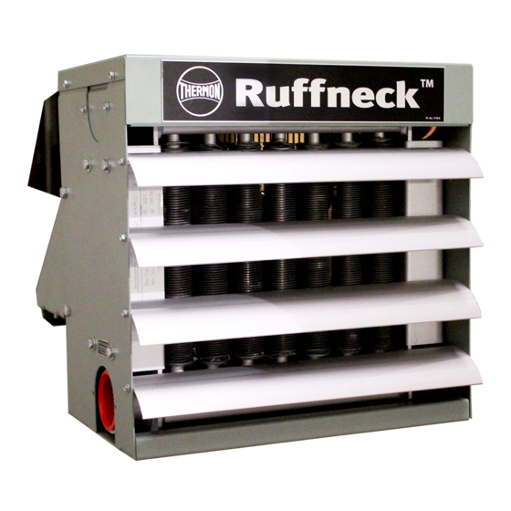
Owner's Manual
Heat-Exchanger Unit Heaters
FR (Frost Resistant) & HP (High Pressure) Series Heaters
This manual covers the installation, maintenance, repair
and parts for all FR and HP series heaters.
CLASSIFICATION
TM
All Ruffneck
FR and HP heaters may be supplied with CSA or UL approved
explosion-proof motors for use in hazardous locations, Divisions 1 & 2, Class I, Groups
C & D and Class II, Groups E, F and G or TEFC (Totally Enclosed Fan Cooled) motors.
Ensure the motor meets the classification requirements.
Warning
Please read all warnings and notices on page 2
TM
Ruffneck
is a key brand of CCI Thermal Technologies Inc.
Part No. 5347-8
Copyright © 2007. All rights reserved
Printed in Canada
Advertisement
Table of Contents

Related Manuals for Ruffneck FR Series


Summary of Contents for Ruffneck FR Series
- Page 1 This manual covers the installation, maintenance, repair and parts for all FR and HP series heaters. CLASSIFICATION All Ruffneck FR and HP heaters may be supplied with CSA or UL approved explosion-proof motors for use in hazardous locations, Divisions 1 & 2, Class I, Groups C &...
-
Page 2: Important Notices
INSTALLATION DESCRIPTION Two basic types of Ruffneck™ Heat Exchanger configurations are available from CCI Thermal Technologies Inc.: FR (Frost Resistant) Series - for steam service only, up to 100 psi (690 kPa) HP (High Pressure) Series - for steam and liquid service up to 400 psi (2,700 kPa) on select models LOCATION OF HEATERS The following guidelines have been established by CCI Thermal Technologies Inc. - Page 3 Basic Mounting Kits (BMK), Hanging Mounting Kits (HMK), Swivel Hanging Mounting Kits (SHMK) or Wall Mounting Kits (WMK) are available for Ruffneck™ heaters. If the strength of the structure is not adequate to support the units, a suitable alternative such as the Ruffneck™ Pipe Mounting Kit (PMK) would be recommended to ensure safe and proper operation.
- Page 4 Typically, mounting heights range from 7 1/2 feet to 12 feet. All Ruffneck™ heaters have louvers installed that allow air flow to be directed from horizontal to 60 degrees or greater downward deflection.
- Page 5 SHUT-OFF VALVE TAP INTO TOP OF MAIN PITCH DOWN FIG.2 UNION UNIT HEATER CONNECTION FOR LOW-PRESSURE STEAM, STEAM UNION OPEN GRAVITY OR VACUUM MAIN FLOAT AND THERMOSTATIC RETURN SYSTEM TRAP UNION 10 IN. Min. NOTES: FULL SIZE DROP LEG (254 mm) 1.
-
Page 6: Physical Dimensions
Physical Dimensions FR/HP12 FR/HP 16 FR/HP 20 FR/HP 24 FR/HP 30 FR/HP 36 16 5/16 (415) 20 5/16 (516) 24 5/16 (618) 28 3/8 (720) 34 7/16 (874) 42 5/8 (1083) 16 3/8 (416) 20 5/16 (517) 24 5/16 (618) 28 1/4 (718) 34 5/16 (872) 42 5/8 (1083) -
Page 7: Electrical Wiring
Electrical Wiring Ruffneck fan-forced unit heaters and heat exchangers may be thermostatically controlled if required. Usually the flow of heat transfer fluid is allowed to pass through the heat exchanger without interruption. The fan motor, in such cases, shuts on and off by an electrical thermostat. Air flow through the heater is thus controlled. A small amount of heat will radiate from the heat exchanger when the fan is inoperative but this is usually tolerable. -
Page 8: Repair And Replacement Procedures
Repair and Replacement Procedures WARNING Disconnect heater from power supply before servicing or repairing heater. Lock the switch in the “OFF” (open) position and/or tag the switch to prevent unexpected power application. This heater should only be serviced by personnel with heating equipment experience. Some components of this heater are heavy and assistance will be required to remove them. -
Page 9: Fan Motor - Removal And Installation
FAN MOTOR - REMOVAL AND INSTALLATION 1. Remove bolts holding motor to the motor mount. 2. Remove the two piece fan guard assembly. 3. Lift the motor assembly off the motor mount. 4. Before removing the fan, measure and record the location of the fan hub on the motor shaft. If fan is difficult to remove, use a gear puller on the fan hub. -
Page 10: Parts List
PARTS LIST FR/HP 12, 16, 20, 24 and 30 models ITEM PART FR, HP 12 FR, HP 16 FR, HP 20 FR, HP 24 FR, HP 30 DESCRIPTION NUMBER NUMBER NUMBER NUMBER NUMBER FR1 CORE ASSEMBLY 2053 2054 2055 2056 2057 HP1 CORE ASSEMBLY 2051... - Page 11 PARTS LIST FR/HP 36 models 10 11 14 17 ITEM PART FR, HP36 ITEM PART FR, HP36 DESCRIPTION NUMBER DESCRIPTION NUMBER FAN GUARD FRAME 3443 FR1 CORE ASSEMBLY 2058 TAPER BUSHING, DRIVE HP1 CORE ASSEMBLY 2044 DRIVEN SHEAVE 1398 HP3 CORE ASSEMBLY 2049 1”...
- Page 12 FRHP Heat-Exchanger Unit Heaters Model Coding SERIES CABINET EXCHANGER TUBE MOTOR CONNECTIONS SIZE MATERIAL COATINGS MATERIAL HEATER SIZES AVAILABLE MODEL & SIZE MOTOR ELECTRICAL VOLTS PHASE HERTZ HP1-12 THRU HP1-36 1 - Pass HP3-12 THRU HP3-36 3 - Pass HP5-16 THRU HP5-36 5 - Pass HP7-24 THRU HP7-36 7 - Pass...
- Page 13 NOTES...
- Page 14 NOTES...
- Page 15 NOTES...
-
Page 16: Maintenance Plan
CCI Thermal Technologies Inc. warrants all Ruffneck™ Unit Heaters against defects in materials and workmanship; damage due to over-torquing of inlet/outlet connections; and for the FR Series units, damage due to inadvertent freeze-up(s). CCI Thermal technologies Inc. will make good or replace any faulty equipment within one year from date of purchase.
Need help?
Do you have a question about the FR Series and is the answer not in the manual?
Questions and answers