Table of Contents
Advertisement
Quick Links
Download this manual
See also:
Owner's Manual
Owner's Manual
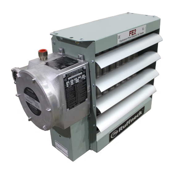
FE2 Series
ISO 9001
Electric Forced Air Heaters for Hazardous Locations
This manual covers the installation, maintenance, repair and replacement parts.
M O D E L C O D I N G
CCI Thermal Technologies Inc.
FE 2 - 2201 50 - 025
5918 Roper Road
Edmonton, Alberta
KILOWATT RATING
T6B 3E1 Canada
HERTZ
PHASE
VOLTAGE
II2 G Ex d IIB T3 Gb
DEMKO 10 ATEX 0910365X
-20°C (-4°F) ≤ Tamb ≤ 40°C (104°F)
2nd GENERATION
MODEL SERIES
W A R N I N G !
READ ALL IMPORTANT NOTICES
Part No. 10525.Rev.8.02
Issue Date: May 2014
Printed in Canada
and VacuCore ® are registered trademarks of CCI Thermal Technologies Inc.
TM
Ruffneck
Copyright © 2014. All rights reserved.
Advertisement
Table of Contents

Related Manuals for Ruffneck FE2 Series


Summary of Contents for Ruffneck FE2 Series
- Page 1 Owner’s Manual FE2 Series ISO 9001 Electric Forced Air Heaters for Hazardous Locations This manual covers the installation, maintenance, repair and replacement parts. M O D E L C O D I N G CCI Thermal Technologies Inc. FE 2 - 2201 50 - 025...
-
Page 2: Heater Maintenance Checklist
HEATER MAINTENANCE CHECKLIST Photocopy this page For Electric Forced Air Heaters for reuse. Heater Model: _________________________ Serial No.: ___________________________ Date of Maintenance: ___________________ Maintenance Done By: _________________ Comments: _________________________________________________________________ __________________________________________________________________________ WARNING Disconnect heater from power supply at fuse box before opening enclosures or servicing heater. Lock the switch in the “OFF”... - Page 3 Photocopy this page for reuse. PERIODIC (before and as required during heating season) 1. CLEAN 2. CHECK � � Finned Tubes Motor for smooth, quiet operation � � Louvers for proper angle and tightness � � Fan Guard All explosion-proof covers for tightness �...
-
Page 4: Important Notices
I M P O R T A N T N O T I C E S WARNING Read and adhere to the following. Failure to do so may result in severe or fatal injury. WARRANTY WILL BE VOID Read and follow all instructions in this manual. shall be certified in type of explosion protection flameproof Heater is to be used only in atmospheres having an enclosure “d”, suitable for the conditions of use and... -
Page 5: Troubleshooting Tips
T R O U B L E S H O O T I N G T I P S Heater is not operating 1.1 Check all fuses in heater control box. 1.2 Check remote disconnect switch and circuit breaker. 1.3 Check voltage supplied to the heater – refer to the heater data plate for voltage requirements. 1.4 Check thermostat by turning it and check continuity with a multimeter. - Page 6 M O U N T I N G MAXIMUM TILT ANGLES (EITHER DIRECTION) The heater must be permanently mounted in a level, upright position for operation. See Figures 3, 4, and 5 1" 0.5" for maximum tilt angles, installation clearances, and (25.4mm) (12.7mm) physical dimensions.
- Page 7 M25 or M32 3. The internal grounding terminal in the control enclosure shall be External Rear View of Heater used as the equipment grounding means. An external bonding opening for Bonding terminal (see Figure 6) is provided for a supplementary bonding field wiring Air exits through connection where local authorities permit or require such a...
- Page 8 TRANSFORMER (tap must match heater voltage) FUSE OPTIONAL PILOT LIGHT CONTACTOR AUTO-RESET AUTO-RESET OPTIONAL OPTIONAL TEMPERATURE TEMPERATURE REDUNDANT ROOM HIGH-LIMIT HIGH-LIMIT TEMPERATURE THERMOSTAT (THERMOWELL) (AMBIENT AIR) HIGH-LIMIT MOTOR ELEMENTS 1-PHASE 220/230/240 WIRING SCHEMATIC TRANSFORMER (tap must match heater voltage) FUSE OPTIONAL PILOT LIGHT...
- Page 9 FE2 TECHNICAL DATA FOR 50 HZ ELECTRIC AIR HEATERS Temperature Model Rise (kW) (AWG) °C °F 3619 FE2-220150-025 2270 11.4 14.3 10.0 18.0 12122 3619 FE2-220150-042 3950 19.1 23.9 17.4 31.3 12123 FE2-220150-063 6050 28.6 35.8 15.2 27.4 12124 3619 3619 FE2-220150-084 8140...
- Page 10 FE2 TECHNICAL DATA FOR 60 HZ ELECTRIC AIR HEATERS Temperature Model Rise (kW) (AWG) °C °F 3619 FE2-220160-025 2270 11.4 14.3 14.4 12122 3619 FE2-220160-042 3950 19.1 23.9 13.9 25.0 12123 3619 FE2-220160-063 6050 28.6 35.8 12.5 22.5 12124 3619 FE2-220160-084 8140 38.2...
-
Page 11: Parts List
PARTS LIST FORCED AIR ELECTRIC HEATERS Item 2.5 – 4.6 kW 6.3 – 10 kW 12.5 – 20 kW 20.9 – 35 kW Description Core Painted: 12694-02 Painted: 12699-02 Painted: 12704-02 Panel, Bottom S.S.: 12704-03 S.S.: 12694-03 S.S.: 12699-03 Painted: 12691-02 Painted: 12696-02 Painted: 12701-02 Panel, Left Side... - Page 12 HEATER ASSEMBLY DIAGRAM Optional built-in thermostat #23 replaces item #16 See control enclosure assembly diagram (below) See high-limit assembly diagram (below) Optional built-in disconnect switch kit CONTROL ENCLOSURE HIGH LIMIT ASSEMBLY DIAGRAM ASSEMBLY DIAGRAM BUS-BAR CONFIGURATION BUS-BAR CONFIGURATION BUS-BAR CONFIGURATION ALL 1-PHASE MODELS ALL 3-PHASE (EXCEPT 380V &...
- Page 13 SPECIFICATIONS FOR ALL 50 HZ MODEL Nominal kW 12.5 14.9 20.9 22.4 to 3.0 to 5.0 to 7.5 to 10 to 13.9 to 20 to 21 to 23.1 Max. Altitude 3,658 2,438 3,048 2,134 3,048 2,134 3,048 2,134 (ft.) 12,000 8,000 10,000 7,000...
- Page 14 SPECIFICATIONS FOR ALL 60 HZ MODEL 12.5 14.9 20.9 22.4 Nominal kW to 3.0 to 5.0 to 7.5 to 10 to 13.9 to 20 to 21 to 23.1 Max. Altitude 3,658 2,438 3,048 2,134 3,048 2,134 3,048 2,134 (ft.) 12,000 8,000 10,000 7,000...
-
Page 15: Repair And Replacement
REPAIR & REPLACEMENT Remove this WARNING core mounting Disconnect heater from power supply at fuse box before opening enclosures b o l t & t w o or servicing heater. Lock the switch in the “OFF” (open) position and/or tag the others on the Loosen switch to prevent unexpected power application. -
Page 16: Printed Circuit Board
P R I N T E D C I R C U I T B O A R D After removing the printed circuit board (P.C. Board) bracket assembly from the control enclosure, separate the P.C. Board from the bracket by cutting off the plastic spacers (see Figure 18). - Page 17 NOTES...
- Page 18 NOTES...
- Page 19 5918 Roper Road, Edmonton, Alberta, Canada T6B 3E1 Phone: (780) 466-3178 Fax: (780) 468-5904 PLEASE ADHERE TO INSTRUCTIONS PUBLISHED IN THIS MANUAL. Failure to do so may be dangerous and may void certain provisions of your warranty. For further assistance, please call: 24 Hr.
- Page 20 DIRECTIVE 2003/108/EC AMMENDMENT TO THE DIRECTIVE 2002/96/EC OF THE EUROPEAN PARLIAMENT AND OF THE COUNCIL on waste electrical and electronic equipment (WEEE). The equipment that you bought is WEEE marked and has required the extraction and use of natural resources for its production. It may contain substances that could impact health and the environment.
Need help?
Do you have a question about the FE2 Series and is the answer not in the manual?
Questions and answers