Advertisement
WARNING!
Read all important information notices.
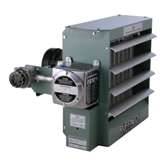
Electric Forced Air Heaters for Hazardous Locations
FX4 Series
Installation, Operation, & Maintenance Instructions
M O D E L C O D I N G
FX 4 - 480 3 60 - 350
VOLTAGE
4th GENERATION
MODEL SERIES
Approved Locations
The Electric Forced Air Heaters are UL listed and/or CSA certified for the following locations:
Class I, Divisions 1 & 2, Groups C & D; Class II, Division 1, Groups E, F, & G; Class II, Division 2 ,
Groups F & G; Class I, Zones 1 & 2, Groups IIA & IIB; Temperature Code T3B 165˚C (329˚F)
(50 Hz & 60 Hz Models)
For details of hazardous locations with potential for explosion, refer to the Canadian Electrical Code,
Part 1, Section 18 or National Electrical Code articles 500-516.
Ruffneck™ and VacuCore ® are registered trademarks of Thermon Heating Systems Inc.
Copyright © 2018. All rights reserved.
KILOWATT RATING
HERTZ
PHASE
Part No.5031.Rev.15.06 August 2018 Printed in Canada
®
ISO 9001
Advertisement
Table of Contents

Related Manuals for Ruffneck FX4 Series


Summary of Contents for Ruffneck FX4 Series
- Page 1 For details of hazardous locations with potential for explosion, refer to the Canadian Electrical Code, Part 1, Section 18 or National Electrical Code articles 500-516. Ruffneck™ and VacuCore ® are registered trademarks of Thermon Heating Systems Inc. Part No.5031.Rev.15.06 August 2018 Printed in Canada...
-
Page 2: Heater Maintenance Checklist
HEATER MAINTENANCE CHECKLIST Photocopy this page For Electric Forced Air Heaters for reuse. Heater Model: _________________________ Serial No.: ___________________________ Date of Maintenance: ___________________ Maintenance Done By: _________________ Comments: _________________________________________________________________ __________________________________________________________________________ WARNING Disconnect heater from power supply at fuse box before opening enclosures or servicing heater. Lock the switch in the “OFF”... -
Page 3: Important Notices
Photocopy ANNUAL (Continued) this page for reuse. □ Check the tightness of all hardware. All nuts and bolts, including mounting hardware, must be tight. □ Turn heater on for a minimum of five minutes. Check for warm air exiting heater through louvers. Crackling or pinging noises within heater during start-up are normal. -
Page 4: Installation
W A R R A N T Y W I L L B E V O I D I F I N S T R U C T I O N S A R E N O T F O L L O W E D I N S T A L L A T I O N The installation instructions provide a general guideline for the installation and wiring of the heater. -
Page 5: Field Wiring
ELECTRICAL WARNING Disconnect heater from power supply at fuse box before opening enclosures or servicing heater. Lock the switch in the "OFF" (open) position and/or tag the switch to prevent unexpected power application. G E N E R A L F I E L D W I R I N G Use only copper conductors and approved explosion-proof wiring The supply conductors, ground conductor, and room thermostat... -
Page 6: Wiring Diagrams
WIRING DIAGRAMS FIGURE 8 FX4 TECHNICAL DATA FOR 50 HZ ELECTRIC AIR HEATERS ® VOLT- NOMINAL MAX. MOTOR HEATER TOTAL MIN. CIRCUIT SUPPLY MAXIMUM TEMPERATURE MODEL WATTAGE NAMEPLATE WATTAGE CURRENT AMPACITY WIRE SIZE FUSE SIZE RISE CORE CONTACTOR CURRENT PART PART NUMBER NUMBER... - Page 7 FX4 TECHNICAL DATA FOR 60 HZ ELECTRIC AIR HEATERS ® MAX. MOTOR NOMINAL HEATER TOTAL MIN. CIRCUIT SUPPLY MAXIMUM VOLT- TEMPERATURE MODEL NAMEPLATE CONTACTOR WATTAGE WATTAGE CURRENT AMPACITY WIRE SIZE FUSE SIZE RISE CORE PART CURRENT PART NUMBER NUMBER °F °C (kW) (AWG)
- Page 8 SPECIFICATIONS FOR ALL 60 Hz MODEL Max. Altitude (ft.) 12,000 8,000 10,000 7,000 10,000 7,000 10,000 7,000 6,000 3,658 2,438 3,048 2,134 3,048 2,134 3,048 2,134 1,829 Air Flow @70°F (CFM) 1750 3600 3950 @21°C /hr.) 1444 2973 6116 6711 Horizontal Air Throw (ft.) 12.2...
- Page 9 SPECIFICATIONS FOR ALL 50 Hz MODEL 3.7&4.2 6.3&7.5 12.5&12.6 14.9&16.7 20.9 22.4 Max. Altitude (ft.) 12,000 8,000 10,000 7,000 10,000 7,000 10,000 7,000 3,658 2,438 3,048 2,134 3,048 2,134 3,048 2,134 Air Flow @70°F (CFM) 1450 3000 @21°C (m3/hr.) 1189 2463 5096 Horizontal Air Throw...
- Page 10 HEATER ASSEMBLY DIAGRAM Optional built-in thermostat replaces item #16 See control enclosure assembly diagram (below) See high-limit assembly diagram (below) CONTROL ENCLOSURE HIGH LIMIT ASSEMBLY DIAGRAM ASSEMBLY DIAGRAM BUS-BAR CONFIGURATION BUS-BAR CONFIGURATION BUS-BAR CONFIGURATION ALL 1-PHASE MODELS ALL 3-PHASE 60 HERTZ & 3-PHASE 50 HERTZ 415 3-PHASE 380 VOLT 50 HERTZ MODELS ONLY VOLT MODEL - 10 -...
-
Page 11: Parts List
P A R T S L I S T F O R C E D A I R E L E C T R I C H E A T E R S Please have model and serial number PART NUMBERS available before calling. -
Page 12: Repair And Replacement
R E PA I R & R E P L A C E M E N T WARNING Disconnect heater from power supply at fuse box before opening enclosures or servicing heater. Lock the switch in the “OFF” (open) position and/or tag the switch to prevent unexpected power application. -
Page 13: Printed Circuit Board
P R I N T E D C I R C U I T B O A R D 1. After removing the printed circuit board (PCB) bracket assembly from the control enclosure, separate the PCB from the bracket by cutting off the plastic spacers (see Figure 17). - Page 14 NOTES - 14 -...
- Page 15 NOTES - 15 -...
- Page 16 PLEASE ADHERE TO INSTRUCTIONS IN THIS MANUAL Failure to do so may be dangerous and may void certain provisions of your warranty. For further assistance, please call 24hr hotline: 1-800-661-8529 (U.S.A. and Canada) Please have model and serial numbers available before calling. WARRANTY No warranty applies to paint fi nishes except for manufacturing defects Under normal use the Company warrants to...
Need help?
Do you have a question about the FX4 Series and is the answer not in the manual?
Questions and answers