Ruffneck FX5 Series Owner's Manual
Electric forced air heaters for hazardous locations
Hide thumbs
Also See for FX5 Series:
- Installation, operation & maintenance instructions manual (44 pages) ,
- Owner's manual (21 pages)
Table of Contents
Advertisement
WARNING!
Read all important information notices on pages 2–4
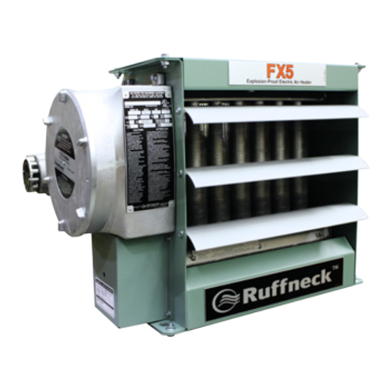
Electric Forced Air Heaters for Hazardous Locations
FX5 Series
Owner's Manual
For installation, maintenance, repair, and replacement parts
Model Coding
FX5 - 480
3
Model
Heater Voltage
Series
208V, 240V,
480V, 600V
5th Generation
Phase
1, 3
approved Locations
C
US
Listed
The Electric Forced Air Heaters are c UL us listed certified for the following locations:
Class I, Divisions 1 & 2, Groups C & D; Class II, Division 1, Groups E, F & G; Class II,
Division 2, Groups F & G; Class I, Zones 1 & 2, Groups IIA & IIB; Temperature Code
T3B 329˚F (165˚C) (50 Hz & 60 Hz Models)
For details of hazardous locations with potential for explosion, refer to the Canadian
Electrical Code, Part 1, Section 18 or National Electrical Code articles 500–516.
60 - 350 - W - T
Hertz
Welded Core
50, 60
T – XT-311 Thermostat with slim
Heater Kilowatts
D – Built-in disconnect
P – Built-in pilot switch
S – 3-way switch
junction box
XT-411 Thermostat with large
junction box
Part No. 9714.Rev.11.03
ISO 9001
H – Unit with high "off" de-energized
ambient temperatures
C – Heresite
coating
®
A – Stainless steel cabinet
U – Continuous fan
B – Low ambient option -50°F (-50°C)
L – Large junction box
Issued July 2016
Printed in Canada
Advertisement
Table of Contents

Related Manuals for Ruffneck FX5 Series


Summary of Contents for Ruffneck FX5 Series
- Page 1 ISO 9001 WARNING! Read all important information notices on pages 2–4 Electric Forced Air Heaters for Hazardous Locations FX5 Series Owner's Manual For installation, maintenance, repair, and replacement parts Model Coding FX5 - 480 60 - 350 - W - T...
-
Page 2: Heater Maintenance Checklist
Photocopy Heater Maintenance Checklist this page Electric Forced Air Heaters for reuse. Heater Model Date of Maintenance Serial Number Maintenance Done By Comments WARNING Disconnect heater from power supply at integral disconnect or fuse Lock the switch in the “OFF” (open) position and/or tag the switch to box before opening enclosures or servicing heater. - Page 3 Photocopy this page for reuse. Periodic (before and as required during heating season) • Clean • Check Motor Motor for smooth, quiet operation Louvers Louvers for proper angle and tightness Finned Tubes All explosion-proof covers for tightness Pressure relief device for signs of leakage. See Figure 1 and refer to the annual section (see below) item 2 for Fan Guard further instructions.
-
Page 4: Important Notices
Photocopy Important Notices this page for reuse. 12. Heater must be kept clean. When operating in a dirty WARNING environment, regularly clean the finned tubes, fan, and fan Read and adhere to the following. Failure to do so may result in guard. -
Page 5: Installation
Troubleshooting Tips (Cont'd) turning the wrong way (the fan must rotate clockwise as Contactor is burned or welded seen from the front of the unit) objects may be stuck in 3.1 Check the contactor for burn marks and blackening. the heat exchanger for drying or warming up – remove Replace the contactor. -
Page 6: Minimum Installation Clearances
Installation General Guideline for Installation and Wiring (Cont'd) • Mounting 22 5/8" MAX. (575mm) The mounting structure must be strong enough to: 10 11/16" ±3/16" The heater must be permanently mounted in a level, upright (271 ±5mm) Ø5/8" (Ø15.5mm) a. Support the heater’s weight position for operation. - Page 7 Electrical frequency amperage, and phase. Supply voltage is to be WARNING within 10% of the data plate voltage. Disconnect heater from power supply at integral disconnect or fuse The heater must be installed by qualified personnel in strict box before opening enclosures or servicing heater. IF INTEGRAL compliance with electrical codes.
- Page 8 Installation General Guideline for Installation and Wiring (Cont'd) • Field Wiring (cont'd) • Final Inspection Heater may be supplied with a factory installed built-in integral Before application of electrical power: disconnect. (See Figure 7B) Check that all connections are secured and comply with the Field Wiring for Integral Disconnect: applicable wiring diagram (see Figure 9 on page 9) and code requirements,...
- Page 9 Installation Wiring Schematics 1-Phase 1-Phase with Optional Pilot Light and 3-Way Switch Optional integral Transformer* Element Contactor disconnect Optional integral Optional 3-Way Switch disconnect Optional Fan B pilot light Auto A&C Fuse Transformer* Optional pilot light Contactor Auto-reset Auto-reset Optional room temperature temperature thermostat...
-
Page 10: Fx5 Technical Data
FX5 Technical Data 50Hz Electric Heaters Temperature Model Rise °F °C FX5-220150-025 2270 11.4 14.3 19.8 11.0 12122 FX5-220150-042 3950 19.1 23.9 33.2 18.4 12123 FX5-220150-063 6050 28.6 35.8 28.5 15.8 12124 FX5-220150-084 8140 38.2 47.8 37.9 21.1 12125 FX5-220150-126* 1450 12.6 12100... - Page 11 FX5 Technical Data 60Hz Electric Heaters Temperature Rise Model °F °C FX5-208160-030 2700 14.4 18.0 19.0 10.5 12116 FX5-208160-050 4700 24.0 30.0 31.6 17.6 12117 FX5-208160-075 7200 36.1 45.1 27.9 15.5 12118 FX5-208160-100* 10.0 9690 48.1 60.1 37.2 20.7 12119 FX5-208360-030 2700 10.4...
-
Page 12: Specifications
Specifications For all 50 Hz Models Nominal kW 3.7 & 4.6 6.3 & 7.5 12.5 & 12.6 14.9 & 16.7 20.9 22.4 12,000 8,000 10,000 7,000 10,000 7,000 10,000 7,000 Maximum Altitude 3,658 2,438 3,048 2,134 3,048 2,134 3,048 2,134 @ 70°F (CFM) 1.450 3.000... - Page 13 Specifications For all 60 Hz Models Nominal kW 12,000 8,000 10,000 7,000 10,000 7,000 10,000 7,000 6,000 Maximum Altitude 3,658 2,438 3,048 2,134 3,048 2,134 3,048 2,134 1,829 @ 70°F (CFM) 1750 3600 Air Flow @ 21°C (m 3 /hr) 1444 2973 6116...
-
Page 14: Parts Assembly Diagram
Parts Assembly Diagram See control enclosure assembly diagram (below) Optional Built-in thermostat replaces item #16 See high limit assembly diagram (below) Optional built-in disconnect switch kit Slim Control Enclosure Large Control Enclosure High Limit Bus-Bar Configuration Bus-Bar Configuration for Bus-Bar Configuration all 1-Phase Models for all 3-Phase for all 3-Phase... -
Page 15: Item Description
FX5 Parts List Forced Air Electric Heaters Please have model and serial number available before calling Item Description 2.5 – 4.6 kW 6.3 – 10 kW 12.5 – 20 kW 20.9 – 35 kW Core Painted: 12694-02 Painted: 12699-02 Painted: 12704-02 Panel, Bottom S.S.: 12694-03 S.S.: 12699-03... -
Page 16: Repair And Replacement
Repair and Replacement WARNING Disconnect heater from power supply at integral disconnect or fuse Lock the switch in the “OFF” (open) position and/or tag the switch to box before opening enclosures or servicing heater. prevent unexpected power application. IF INTEGRAL DISCONNECT IS BEING SERVICED, verify that power This heater should only be serviced by personnel with heating and has been disconnected at fuse box or main panel. - Page 17 To reassemble, place motor assembly onto motor mount and • Motor, Fan, & Fan Guard fasten the fan guard to cabinet. Remove bolts holding the motor to the motor mount. On units Simultaneously engage and tighten both ends of conduit #1 into with a built-in thermostat, remove the bolts on the back of the enclosures.
-
Page 18: Printed Circuit Board
Repair and Replacement • Printed Circuit Board After removing the printed circuit board (P.C. Board) bracket assembly from the control enclosure, separate the P.C. Board from the bracket by cutting off the plastic spacers (see Figure 18). 1/16" to 3/16" Reinstall a new factory supplied P.C. - Page 19 Notes NOTES...
- Page 20 PLEASE ADHERE TO INSTRUCTIONS IN THIS MANUAL Failure to do so may be dangerous and may void certain provisions of your warranty. For further assistance, please call 24hr hotline: 1-800.661-8529 (U.S.A. and Canada) Please have model and serial numbers available before calling. WARRANTY No warranty applies to paint finishes except for manufacturing Under normal use the Company warrants to...
Need help?
Do you have a question about the FX5 Series and is the answer not in the manual?
Questions and answers