Table of Contents
Advertisement
Available languages
Available languages
Quick Links
IMPORTANT INSTRUCTIONS - SAVE THESE INSTRUCTIONS
Read all instructions before installing or using the heater. Please adhere to instructions published in this manual.
Failure to do so may be dangerous and may void certain provisions of your warranty.
Regular Duty Forced Air Unit Heaters
RGE Series
Owner's Manual
Installation, Operation, & Maintenance Instructions
Model Coding
RGE
Model
Series
Ruffneck™ is a registered trademark of Thermon Heating Systems Inc.
Copyright© 2018. All rights reserved.
2 0
3
Kilowatts
Voltage
02 - 2 kW
2 - 208
03 - 3 kW
3 - 240
04 - 4 kW
5 - 347
05 - 5 kW
6 - 416
07 - 7.5 kW
7 - 480
10 - 10 kW
8 - 600
15 - 15 kW
20 - 20 kW
25 - 25 kW
30 - 30 kW
40 - 40 kW
C
T
Contactor
Thermostat
Energy
(Optional)
(Optional)
Management
Controller
(Optional)
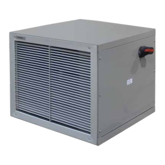
RGE heater with optional disconnect
L
-
D
Other Options
B - Epoxy painted fan blade and motor
D - Disconnect switch
F - Fan only switch
K - Fused control circuit
M - Manual reset high limit
N - Low voltage relay (24 V)
V - 120V control voltage (240 V is standard)
Part No.MI280.Rev.4.01
August 2018 Printed in Canada
®
C
US
ISO 9001
Advertisement
Chapters
Table of Contents

Related Manuals for Ruffneck RGE Series


Summary of Contents for Ruffneck RGE Series
- Page 1 V - 120V control voltage (240 V is standard) 20 - 20 kW 25 - 25 kW 30 - 30 kW 40 - 40 kW Part No.MI280.Rev.4.01 August 2018 Printed in Canada Ruffneck™ is a registered trademark of Thermon Heating Systems Inc. Copyright© 2018. All rights reserved.
-
Page 2: Table Of Contents
TABLE OF CONTENTS A. Important Notices B. Installation Location ........................4 Mounting ........................4 Electrical ........................5 Sample Wiring Schematics - RGE Series Heater ............5 C. Operation General ......................... 8 D. Repair & Replacement Heating Elements ......................8 Fan ..........................8 Thermal Cut-Out ...................... -
Page 3: Important Notices
IMPORTANT NOTICES Disconnect heater from power supply at disconnect or CAUTION. This symbol indicates a potentially fuse box before opening enclosures or servicing heater. IF hazardous situation, which, if not avoided, may result in DISCONNECT IS BEING SERVICED, verify power has been personal injury or damage to the equipment. -
Page 4: Installation
INSTALLATION General Guideline for Installation and Wiring All applicable codes must be adhered to. For optimum The single bolt mounting is not designed for high dynamic performance, the heater should be installed as follows: loads that can occur during transportation. For heaters that are to be installed prior to transportation, it is recommended that temporary blocking or strapping be used to limit Location... -
Page 5: Electrical
Any thermostat used with this heater must be: UL listed or CSA approved Rated for 240 volts minimum and 5 amps minimum. Figure 2A – RGE Series 2 – 10 kW wiring schematic with hi-limit option. 208 V and 240 V models. - Page 6 Figure 2B – RGE Series 2 – 10 kW wiring schematic with hi-limit and fused control circuit options. 208/240/480/600 V models. Figure 2C – RGE Series 2 – 10 kW wiring schematic with hi-limit, contactor, built-in thermostat, fan only switch options. 208 - 240 V models.
- Page 7 Figure 2F - RGE Series 15 – 40 kW wiring schematic with hi-limit and contactor options. 208 – 240 V models. Figure 2G - RGE Series 15 – 40 kW wiring schematic with hi-limit, contactor, transformer and fused control circuit options. 208 – 600 V...
-
Page 8: Operation
OPERATION General To operate heater, ensure power supply is properly During normal operation, the thermal cut-out control should not connected as specified in the wiring schematic (refer to cycle the heater ON and OFF. If cycling occurs, check to see Figures 2A –... -
Page 9: Parts List
PARTS LIST Item Description Cabinet box assembly Louver assembly Motor mount Motor Fan blade PARTS LIST Cover panel ITEM DESCRIPTION Rear grille CABINET BOX ASSEMBLY LOUVER ASSEMBLY Non-finned (2–10 kW), MOTOR MOUNT Finned element (15–40 kW) MOTOR Thermostat - SPST FAN BLADE Thermostat knob COVER PANEL... - Page 10 Table 3 – Parts List: Heating Elements Item Description Part Number Item Description Part Number Cabinet box assembly Contact Factory KXF11008-37 KXF11008-14 2 – 10 B11022-01 Louver assembly — IXS11006-38 15 – 40 B11022-02 IXS11006-17 2 – 10 B11026-01 Heating Elements Motor mounting Bracket —...
-
Page 11: Troubleshooting Tips
TROUBLESHOOTING TIPS Heater is not operating. Heater is operating but no heat is present. Check all fuses. If equipped with a “FAN ONLY” switch, ensure the switch is in the “ON” position. Check disconnect switch. Check the control voltage to the contactor coil, if unit is Check voltage supplied to the heater –... -
Page 12: The Ground Fault Interrupter (Gfi) Trips On The Main Panel, Or Heater Blows Fuses
The Ground Fault Interrupter (GFI) trips on the main panel, or heater blows fuses. Check that you have a fuse of the proper amperage rating. Check for loose or frayed wiring. If condition is not observable, send heater in for repair. The fan is turning but very little air comes from the front of the heater. -
Page 13: Technical Data
TECHNICAL DATA Table 6 – Technical Data Air Flow Temp. Rise Basic Unit with: Amps Basic Unit Thermostat Contactor & (Btu/hr) m³/min ºF ºC Contactor Ph 1 Ph 3 (1 Ph only) Thermostat 1 or 3 RGE022 RGE022C RGE022T RGE022CT 11.1 208/240 (6824) -
Page 14: General Specifications
GENERAL SPECIFICATIONS Table 7 – General Specifications Nominal kW Fan Diameter 1040 1260 1500 1500 1500 Air Delivery m³/min Horizontal Throw Normal Mounting 12.0 Height* (to underside) Shipping Weight *Recommended mounting height to ensure warm air reaches the floor. -
Page 15: Heater Maintenance Instructions
HEATER MAINTENANCE INSTRUCTIONS Heater Model Date of Maintenance Serial Number Maintenance Done By Comments Periodic (before and as required during heating season) Clean - use compressed air only Mounting & Motor Check All mounting hardware condition and tightness … Heating Elements Inlet Grille …... - Page 16 PLEASE ADHERE TO INSTRUCTIONS IN THIS MANUAL Failure to do so may be dangerous and may void certain provisions of your warranty. For further assistance, please call 24hr hotline: 1-800-661-8529 (U.S.A. and Canada) Please have model and serial numbers available before calling. WARRANTY No warranty applies to paint fi nishes except for manufacturing defects Under normal use the Company warrants to...
- Page 17 30 - 30 kW V - Tension de commande 120 V 40 - 40 kW (240 est standard) Part No.MI280.Rev.4.01 août 2018 Imprimé au Canada Ruffneck est une marque déposée de Thermon Heating Systems Inc. Droit d’auteur © 2018 Tous droits réservés.
- Page 18 TABLE DES MATIÈRES A. Avis importants B. Installation Emplacement .........................20 Installation ........................20 Électricité ........................21 Schémas de câblage typiques – Aérotherme de série RGE ..........22 C. Fonctionnement Généralités ........................24 D. Réparation et rechange Éléments chauffants ......................24 Ventilateur ........................24 Protecteur thermique ......................24 E.
-
Page 19: Avis Importants
AVIS IMPORTANTS ATTENTION. Ce symbole indique une situation Ne faites pas fonctionner l’aérotherme dans des potentiellement dangereuse qui, si elle n’est pas environnements humides. évitée, peut causer des blessures ou des ATTENTION dommages à l’équipement. Respectez les dégagements autour de l’appareil lors de l’installation, suivant ce manuel. -
Page 20: Installation
INSTALLATION Directives générales pour l’installation et le raccordement électrique. Respectez toutes les normes en vigueur. Pour une performance optimale, l’aérotherme doit être installé en respectant les directives L’aérotherme doit être installé de façon permanente. suivantes: La base d’installation doit être suffisamment solide pour: Supporter le poids de l’aérotherme. -
Page 21: Électricité
Un serrage adéquat du boulon d’installation électriques ou les fils d’un thermostat externe. Deux impliquera une compression totale de la rondelle pastilles défonçables pour conduits de ½ po ou ¾ po se de blocage fendue ainsi qu’une inspection du bon trouvent sur les appareils de 2 –... -
Page 22: Schémas De Câblage Typiques - Aérotherme De Série Rge
Si les schémas de câblage des Figures 2A – 2F, page 21 – 23 ne correspondent pas à votre configuration, vérifiez la face interne du panneau d'accès de l’aérotherme pour le schéma de câblage spécifique. Par ailleurs, tous les schémas de câblage peuvent être trouvés sur le site: www.ruffneck.com CÂBLAGE IN-SITU CÂBLAGE D’USINE... - Page 23 Schémas de câblage typiques – Aérotherme de série RGE CÂBLAGE D’USINE CÂBLAGE IN-SITU Contacteur externe Contacteur externe Caractéristique de l’interrupteur de sécurité: 600 V, 10 A résistif Interrupteur ou Interrupteur ou thermostat thermostat Circuit de commande 240 V CA, 1 A résistif 240 V CA, 1 A résistif 1 Phase 3 Phase...
-
Page 24: Fonctionnement
FONCTIONNEMENT Pendant le fonctionnement normal de l’aérotherme, Généralités le protecteur thermique ne doit pas s’engager et Pour faire fonctionner l’aérotherme, vérifiez que mettre l’appareil dans un cycle d’arrêt et de marche. Si l’alimentation est raccordée comme il faut, selon les l’aérotherme se met en cycle d’arrêt/marche, vérifiez si le spécifications du schéma de câblage (voir Figures 2A –... -
Page 25: Liste Des Pièces De Rechange
LISTE DES PIÈCES DE RECHANGE Article Description Enceinte Déflecteurs Support de moteur Moteur Pale de ventilateur PARTS LIST Panneau-couvercle ITEM DESCRIPTION Grille arrière CABINET BOX ASSEMBLY LOUVER ASSEMBLY Éléments chauffants sans ailettes MOTOR MOUNT (2–10 kW), et avec ailettes (15–40 kW) MOTOR Thermostat –... - Page 26 Tableau 3 – Liste des pièces de rechange: Élément chauffant Article Description Part Number Article Description Part Number Enceinte Contact Factory KXF11008-37 2 – 10 B11022-01 KXF11008-14 Déflecteurs — 15 – 40 B11022-02 IXS11006-38 2 – 10 B11026-01 IXS11006-17 Éléments chauffants Support de moteur —...
-
Page 27: Conseils De Dépannage
CONSEILS DE DÉPANNAGE L’aérotherme ne fonctionne pas. L’aérotherme fonctionne, mais il n’y a pas de chauffage. Vérifiez tous les fusibles. Si l’aérotherme est muni d’un commutateur « Ventilateur seul (« FAN ONLY »), vérifiez que le commutateur est sur la Vérifiez l’interrupteur. -
Page 28: Le Disjoncteur Différentiel De Fuite À La Terre (Ddft) Se Déclenche Dans Le Panneau
Le disjoncteur différentiel de fuite à la terre (DDFT) se déclenche dans le panneau principal, ou l’aérotherme fait sauter les fusibles. Vérifiez que les fusibles sont adéquats pour l’intensité nominale du courant. Vérifiez que les câbles ne sont pas desserrés ou abimés. S’il est impossible d’établir la cause du problème, renvoyez l’aérotherme pour réparation. -
Page 29: Données Techniques
DONNÉES TECHNIQUES Tableau 6 – Données techniques Débit d’air Temp. Hausse Modèle de base avec Amp. Modèle de Thermostat Contacteur et base (Btu/hr) Pi³/min m³/min ºF ºC Contacteur (1 Phase Ph 1 Ph 3 thermostat uniquement) 1 or 3 RGE022 RGE022C RGE022T RGE022CT... -
Page 30: Caractéristiques Générales
CARACTÉRISTIQUES GÉNÉRALES Tableau 7 – Caractéristiques générales Nominale kW Diamètre du ventilateur pi³/min 1040 1260 1500 1500 1500 Débit d’air m³/h Portée horizontale Hauteur de 12.0 montage normale à l’horizontale* (dessous de l’appareil) Poids à l’expédition Remarque: Hauteur de montage recommandée pour assurer que l’air chauffé arrive au plancher. -
Page 31: Instructions Pour L'entretien De L'aérotherme
INSTRUCTIONS POUR L’ENTRETIEN DE L’AÉROTHERME Modèle de l’aérotherme Date de l’entretien Numéro de série Entretien effectué par Commentaires Périodique (avant la saison de chauffage, ainsi qu’au besoin pendant la saison de chauffage) Nettoyer – utilisez uniquement de l’air comprimé Montage et vérification État et tension de la totalité... - Page 32 VEUILLEZ VOUS CONFORMER AUX INSTRUCTIONS CONTENUES DANS CE MANUEL. Chauffages pour les environnements les plus rigoureux Tout manquement à ces dernières pourrait s’avérer dangereux et invalider certaines dispositions de votre garantie. Pour obtenir une aide supplémentaire, veuillez appeler: 1-800-661-8529 (U.S.A. and Canada) Merci de préparervos numéros de modèle et de série avante d’appeler.
Need help?
Do you have a question about the RGE Series and is the answer not in the manual?
Questions and answers