
Related Manuals for CYP CH-U331TR


Summary of Contents for CYP CH-U331TR
- Page 1 CH-U331TR UHD HDMI/DP to IP AV over IP Transceiver Operation Manual Operation Manual...
- Page 3 DISCLAIMERS The information in this manual has been carefully checked and is believed to be accurate. Cypress Technology assumes no responsibility for any infringements of patents or other rights of third parties which may result from its use. Cypress Technology assumes no responsibility for any inaccuracies that may be contained in this document.
- Page 4 SAFETY PRECAUTIONS Please read all instructions before attempting to unpack, install or operate this equipment and before connecting the power supply. Please keep the following in mind as you unpack and install this equipment: • Always follow basic safety precautions to reduce the risk of fire, electrical shock and injury to persons.
-
Page 5: Table Of Contents
CONTENTS 1. Introduction ............1 2. Applications ............. 2 3. Package Contents ........... 2 4. System Requirements ........2 5. Features............3 6. Operation Controls And Functions ....4 6.1 Front Panel ..........4 6.2 Rear Panel........... 6 6.3 IR Cable Pinouts.......... 8 6.4 RS-232 Pinout and Defaults ...... -
Page 6: Introduction
1. INTRODUCTION This UHD HDMI/DP to IP AV over IP Transceiver forms a part of a multi- function video and data extension system. Every Transceiver can be configured to function as either a transmitter or a receiver, enhancing the flexibility of any installation. Both HDMI and DisplayPort video inputs are provided with support for resolutions up to 4K (4K@30Hz 4:4:4 or 4K@60Hz 4:2:0) along with analog audio, USB 2.0, IR and serial data extension using the TCP/IP protocol over regular Gigabit Ethernet networks (Cat.5e/6/7... -
Page 7: Applications
2. APPLICATIONS • HDMI, DisplayPort, USB, Audio, IR, and RS-232 extension • Broadcasting a system over a standard Ethernet connection • Multimedia display on a large number of displays via multicast • Hotel or convention center display multi-monitor broadcast • Long distance data and video transmission via cascading •... -
Page 8: Features
5. FEATURES • HDMI 2.0 and DVI 1.0 compatible • HDCP 1.x & 2.2 compliant • 1 HDMI input, 1 DisplayPort input • 1 HDMI output (Functions as local monitor output in Transmitter mode) • Video, audio, and control transmission over TCP/IP in Unicast (point-to- point) or Multicast (single-to-many) modes •... -
Page 9: Operation Controls And Functions
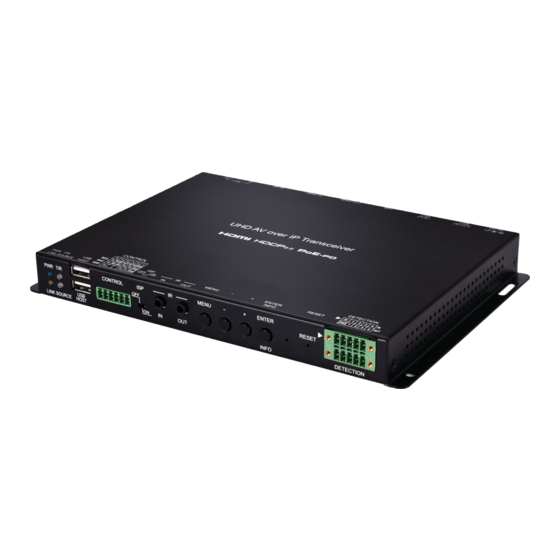
6. OPERATION CONTROLS AND FUNCTIONS 6.1 Front Panel CONTROL MENU ENTER PWR T/R RESET INFO DETECTION LINK SOURCE HOST PWR LED: This LED will flash while the unit is powering on and will illuminate solidly once it is ready to be used. T/R LED: This LED indicates if the unit is in Transmitter (green LED) or Receiver (red LED) Mode. - Page 10 CONTROL 6-pin Terminal Block: Connect directly to your PC/laptop to send commands to serial devices connected to routed transmitter/ receivers. Serial mode can be switched between RS-232, RS-422, and RS-485 using the OSD menu. Note: When in Transmitter Mode, and set to multicast output, every connected receiver unit can extend serial commands through the transmitter and commands sent from the transmitter side will be sent through all associated receivers.
-
Page 11: Rear Panel
Connect the 4 bottom pins to devices with trigger activation functionality, such as window security alarms, smoke detectors, or door buzzers, to extend their current state to a connected transmitter/receiver. Note: This is designed to be connected to individual trigger devices and is NOT compatible with the Trigger Control Keypad. - Page 12 DP IN Port: Connect to DisplayPort source equipment such as a PC or laptop. LINE IN Port: Connect to the stereo analog output of a device such as a CD player or PC. Note: When a live audio source is connected to the Line In port, it will be automatically embedded into the transmitted signal, and will completely replace any existing HDMI audio when the unit is in “Auto”...
-
Page 13: Ir Cable Pinouts
6.3 IR Cable Pinouts IR Extender IR Blaster Cable Cable Power Infrared Infrared Power Not Used Ground 6.4 RS-232 Pinout and Defaults Serial Port Default Settings Baud Rate 115200 Data Bits Parity Bits None Stop Bits Flow Control None Control Port (RS-232 mode) Control Port (RS-422 mode) 6-pin Terminal Block 6-pin Terminal Block... -
Page 14: Osd Menu
6.5 OSD Menu Many functions of this unit can be controlled by using the OSD (On Screen Display) which is activated by pressing the MENU button on the front of the unit. Use the + (PLUS), − (MINUS), and ENTER buttons to navigate the OSD menu. - Page 15 EDID 2ND LEVEL 3RD LEVEL VoIP EDID [Display current EDID DP In EDID data for each port] HDMI In EDID 1) EDID: Selecting any of the input ports will display the current EDID data being provided to that port. HDCP 2ND LEVEL 3RD LEVEL HDMI HDCP...
- Page 16 DEVICE SETTING 2ND LEVEL 3RD LEVEL TRANSMITTER Status Receiver HDMI IN Input DP In VoIP (Receiver mode only) Local Priority HDMI 1) Status: Set the operational mode of the transceiver. After changing the operation mode, the unit will automatically reboot. 2) Input: Select the preferred input source, HDMI, DisplayPort, or VoIP.
-
Page 17: Webgui Control
6.6 WebGUI Control All major functions of the unit, including status, streaming method, streaming channel selection, output resolution, video wall configuration, EDID management, Ethernet settings, and reset/firmware functions are controllable via multiple tabs in the WebGUI interface allowing for reasonably intuitive operation. -
Page 18: System Tab
6.6.1 System Tab The System tab contains 4 windows that provide access to firmware version information, a firmware update interface, utilities for rebooting and resetting the unit, basic EDID management, Telnet command entry, and a variety of statistics and information about the operational state of the unit. 1) Version Information Window: This window displays detailed information about the current firmware version. - Page 19 3) Utilities Window: The Utilities window allows users to reset the unit back to the factory defaults by clicking “Factory Default”. The unit may be rebooted (without resetting settings) by pressing the “Reboot” button. If the EDID received from the primary receiver unit (selected via a checkbox on the preferred receiver in multicast mode) has compatibility issues with the connected HDMI source, the internal HDMI EDID (up to 4K30 w/audio) can be selected.
- Page 20 4) Statistics Window: The Statistics window shows all available information about the operational status of the unit, including current Host ID Name, SN, Ethernet information, MAC address, unicast/multicast mode, link status and mode.
-
Page 21: Video Wall Tab
6.6.2 VIDEO WALL TAB The Video Wall tab allows user to design, edit and manipulate a video wall system created using multiple receiver units connected to identical displays. The bezel and video size of the displays being used, as well as the horizontal and vertical monitor count, is defined here. - Page 22 „ OW (Outer Width): This is the horizontal measurement of the display’s outer case. „ OH (Outer Height): This is the vertical measurement of the display’s outer case. „ VW (Video Width): This is the horizontal measurement of the display’s video screen.
- Page 23 wall consists of an equal number of horizontal and vertical monitors (for example: 2×2 or 3×3), however it is possible to create video walls using this system with a wider variety of dimensions as long as the end result is still a rectangle (for example: 5×1 or 2×3). Both horizontal and vertical dimensions are limited to a maximum of 16 displays.
- Page 24 of the video wall regardless of the source’s original aspect ratio. - Selecting “Stretch Out” will zoom the video until the video wall is filled in all 4 dimensions while maintaining the aspect ratio of the original source. „ Clockwise Rotate: Set the rotation of the video output to 0, 180 or 270 degrees.
-
Page 25: Network Tab
6.6.3 Network Tab The Network tab provides control over the transceiver’s broadcast or reception channel, IP configuration, and network broadcast mode. Changes made to the network settings will require a reboot of the unit. After clicking on “Apply” please follow the reboot instructions in the WebGUI. Note: If the IP address is changed then the IP address required for WebGUI access will also change accordingly. - Page 26 1) Channel Setup: Use the dropdown to select the broadcast or reception channel for the transceiver. All receivers on the local network will receive video and data content from the transmitter that set to the same channel. The available channel range is from 0 to 255. Note: Every transmitter within the same local network MUST be assigned a different broadcast channel in order to avoid conflicts.
-
Page 27: Functions Tab
„ Unicast: This mode uses a discrete video stream between the transmitter and every connected receiver and is ideal for simple, point-to-point, streaming setups. This mode uses considerably more bandwidth than Multicast mode when multiple receivers are being used, however it does not require a network switch that supports IGMP snooping. - Page 28 Note: While it is generally suggested to select “Unlimited” when streaming 4K video sources, the amount of bandwidth required can be very large and will limit the number of concurrent video streams. „ Maximum Framerate: Adjusting this slider will set the percentage of frames from the source video to encode (2–100%).
- Page 29 „ Video Loss Options: Use the drop down to set the length of time to wait for a lost source to return before showing the “Link Lost” screen. Available options are: 3, 5, 10, 20, 30, 60 seconds, or Never Timeout. If the “Turn off screen”...
- Page 30 „ Operation Mode: Sets the USB extension mode. Available options are Auto, Active on link (Unicast optimized), and Active per request (Multicast optimized). Auto mode is set by default and will automatically select the correct mode depending on the broadcast mode of the unit.
- Page 31 6) Trigger Status (Both Modes): This section shows the current state of all input and output trigger pins on the unit. “L” will be displayed for pins that are currently “Low” and “H” will be displayed for pins that are currently “High”.
-
Page 32: Telnet Control
6.7 Telnet Control Before attempting to use Telnet control, please ensure that both the unit and the PC are connected to the same active networks. To Access the Command Line Interface (CLI) Windows 7 Click Start, type “cmd” in the search field, and press Enter. -
Page 33: Telnet Commands
6.8 Telnet Commands COMMAND Description and Parameters System Commands help Show the full command list. help N1 Show help details about the specified command. N1 = {Command name} get_hardware_version Show the current hardware version. get_firmware_version Show the current firmware version. set_device_name N1... - Page 34 COMMAND Description and Parameters Network Configuration get_ipconfig Show the current IP configuration. set_ip_mode N1 Set the IP configuration mode. Available values for N1: [Static IP mode] [DHCP mode] [Auto IP mode] get_ip_mode Show the current IP configuration mode. set_ip_address N1 Set the static IP address.
- Page 35 COMMAND Description and Parameters set_net_mode N1 Set the network broadcast mode. Available values for N1: [Unicast mode] [Multicast mode] get_net_mode Show the current network broadcast mode. set_jumbo_mtu N1 Enable/disable the jumbo frame MTU. Available values for N1: [Disabled] [Enabled] get_jumbo_mtu Show the jumbo frame MTU state.
- Page 36 COMMAND Description and Parameters video_source_voip Select the current streaming channel as the video input source. Note: Receiver mode only. a N1 Set the transmitter’s local audio streaming source. Available values for N1: [Digital audio source] [Analog audio source] AUTO [Automatic audio selection] Discovery Service Commands set_showme N1...
- Page 37 COMMAND Description and Parameters get_quality Show the current picture quality mode. set_hdcp_allow N1 Enable/disable HDCP encrypted source support. Available values for N1: [Disabled] [Enabled] get_hdcp Show the current HDCP support state. set_bandwidth N1 Set the broadcast stream bandwidth maximum. Available values for N1: [50 Mbps] [100 Mbps] [200 Mbps]...
- Page 38 COMMAND Description and Parameters set_vw_layout N1 N2 {N3} Set the video wall total horizontal and vertical display count for the specified receiver. N1 = 1~16 [Horizontal display count] N2 = 1~16 [Vertical display count] N3 = 0~255 [Target receiver ID {Optional}] Note: The target receiver ID number can be obtained by turning on the Video Wall OSD.
- Page 39 COMMAND Description and Parameters set_vw_hscale N1 {N2} Set the video wall display horizontal zoom amount for the specified receiver. N1 = 0~99999 [Zoom amount in 1 pixel units] N2 = 0~255 [Target receiver ID {Optional}] Note: The target receiver ID number can be obtained by turning on the Video Wall OSD.
- Page 40 COMMAND Description and Parameters set_vw_delay N1 {N2} Set the video wall display delay compensation value for the specified receiver. N1 = 0~99999 [Delay in microseconds] N2 = 0~255 [Target receiver ID {Optional}] Note: The target receiver ID number can be obtained by turning on the Video Wall OSD.
- Page 41 COMMAND Description and Parameters set_rx_channel N1 {N2} Select a content type from the specified AVoIP transmission channel to receive for output or select all content from that channel. N1 = 0~255 [Transmission channel] Available values for N2: [Video content] [Audio content] [USB content] [Serial data content] [IR content]...
- Page 42 COMMAND Description and Parameters set_output_res N1 Set the output resolution. Available values for N1: [640×480@60Hz] [800×600@60Hz] [1024×768@60Hz] [1280×768@60Hz] [1280×800@60Hz] [1280×1024@60Hz] [1360×768@60Hz] [1366×768@60Hz] [1440×900@60Hz] [1400×1050@60Hz] [1600×900@60Hz] [1600×1200@60Hz] [1680×1050@60Hz] [1920×1200@60Hz] [Bypass] [Native] [480i@60Hz] [576i@50Hz] [480p@60Hz] [576p@50Hz] [720p@60Hz] [720p@50Hz] [720p@30Hz] [720p@25Hz] [1080i@60Hz] [1080i@50Hz] [1080p@60Hz] [1080p@50Hz] [1080p@30Hz]...
- Page 43 COMMAND Description and Parameters set_vw_osd N1 Enable/disable the video wall OSD to display the receiver ID number on the connected display. Available values for N1: [Disable OSD] [Enable OSD] get_vw_osd Show the current video wall OSD state. set_vw_layout N1 N2 Set the video wall’s total horizontal and vertical display count.
- Page 44 COMMAND Description and Parameters set_vw_bc N1 N2 N3 N4 Set the video wall bezel compensation values for the display connected to this unit. N1 = 0~99999 [Video width] N2 = 0~99999 [Total display width] N3 = 0~99999 [Video height] N4 = 0~99999 [Total display height] get_vw_bc...
- Page 45 COMMAND Description and Parameters get_vw_shift Show the current video output shift of the display connected to this unit. set_vw_delay N1 Set the video wall display delay compensation value for this unit. N1 = 0~99999 [Delay in microseconds] get_vw_delay Show the current video wall display delay compensation value for this unit.
- Page 46 COMMAND Description and Parameters Serial Commands set_serial_baud N1 Set the serial baud rate. Available values for N1: [300 baud] [600 baud] [1200 baud] [2400 baud] [4800 baud] [9600 baud] [19200 baud] [38400 baud] [57600 baud] [115200 baud] get_serial_baud Show the current serial baud rate. set_serial_bits N1...
- Page 47 COMMAND Description and Parameters set_serial_stop N1 Set the serial stop bits. Available values for N1: [1 bit] [2 bits] get_serial_stop Show the current serial stop bits. Note: Commands will not be executed unless followed by a carriage return. Commands are not case-sensitive.
-
Page 48: Connection Diagram
7. CONNECTION DIAGRAM Laptop/PC Security Window DVD/Blu-ray Player Input & Output 1.5m 60° HDMI Input 60° PWR T/R CONTROL MENU ENTER RESET LINK SOURCE HOST INFO TRIGGER LINE DC 5V USB DEVICE LAN (POE) HDMI OUT HDMI IN DP IN DisplayPort Input RJ-45 or Fiber Ethernet Network Switch (PoE) -
Page 49: Specifications
8. SPECIFICATIONS 8.1 Technical Specifications HDMI Bandwidth 10.2Gbps DisplayPort Bandwidth 10.2Gbps Ethernet Bandwidth 1Gbps Input Ports 1×HDMI (Type-A) 1×DisplayPort 1×Stereo Audio (3.5mm) Output Ports 1×HDMI (Type-A) 1×Stereo Audio (3.5mm) Pass-through Ports 1×IR Extender (3.5mm) 1×IR Blaster (3.5mm) 2×USB 2.0 (Type-A) 1×USB 2.0 (Type-B) 8×Trigger (10-pin Terminal Block) Pass-through/Control Port... - Page 50 Chassis Color Black Operating Temperature 0˚C – 40˚C/32˚F – 104˚F Storage Temperature -20˚C – 60˚C/-4˚F – 140˚F Relative Humidity 20 – 90% RH (Non-condensing) Power Consumption 18.92W...
-
Page 51: Video Specifications
8.2 Video Specifications Input Output AVoIP Supported Resolutions (Hz) HDMI HDMI 720×400p@70/85 640×480p@60/72/75/85 720×480i@60 720×480p@60 720×576i@50 720×576p@50 ... - Page 52 Input Output AVoIP Supported Resolutions (Hz) HDMI HDMI 2560×1440p@60RB 2560×1600p@60RB 2048×1080p@24/25/30 2048×1080p@50/60 3840×2160p@24/25/30 3840×2160p@50/60 (4:2:0) 3840×2160p@24, HDR10 ...
-
Page 53: Audio Specifications
8.3 Audio Specifications 8.3.1 Digital Audio HDMI Input / Output LPCM Max Channels 8 Channels Sampling Rate (kHz) 32, 44.1, 48, 88.2, 96, 176.4, 192 Bitstream Supported Formats Standard DisplayPort Input LPCM Max Channels 8 Channels Sampling Rate (kHz) 32, 44.1, 48, 88.2, 96, 176.4, 192 Bitstream Supported Formats Standard... -
Page 54: Analog Audio
8.3.2 Analog Audio Analog Input Max Audio Level 2Vrms Impedance 10kΩ Type Unbalanced Analog Output Max Audio Level 2Vrms THD+N < −66dB@0dBFS 1kHz (A-wt) > 80dB@0dBFS Frequency Response < ±25dB@20Hz~20kHz Crosstalk < −60dB@10kHz Impedance 1kΩ Type Unbalanced... -
Page 55: Avoip Audio Availability
8.3.3 AVoIP Audio Availability Unicast Data Transmission Mode Connected Audio Sources Audio Source Output HDMI/DP LINE IN LINE IN HDMI OUT LINE OUT LINE OUT IN (TX) (TX) (RX) (RX) (TX) (RX) ● ● ● ■ ■ ■ ● ■... -
Page 56: Cable Specifications
8.4 Cable Specifications 1080p 4K30 4K60 (4:4:4) (4:4:4) Cable Length 8-bit 12-bit 8-bit 8-bit High Speed HDMI Cable HDMI Input HDMI Output DisplayPort Cable DisplayPort Input Ethernet Cable Cat.5e/6 100m Cat.6A/7 100m Fiber Cable Multi-mode Fiber (OM3) 300m ... -
Page 57: Acronyms
9. ACRONYMS ACRONYM COMPLETE TERM Analog-to-Digital Converter ASCII American Standard Code for Information Interchange AVoIP Audio/Video over IP Cat.5e Enhanced Category 5 cable Cat.6 Category 6 cable Cat.6A Augmented Category 6 cable Cat.7 Category 7 cable Command-Line Interface Digital-to-Analog Converter Decibel DHCP Dynamic Host Configuration Protocol... - Page 58 ACRONYM COMPLETE TERM Media Access Control MJPEG Motion JPEG Megahertz Optical Multi-mode Optical On-Screen Display Power over Ethernet Signal-to-Noise Ratio Transmission Control Protocol THD+N Total Harmonic Distortion plus Noise 4K UHD 4K Ultra-High-Definition (10.2Gbps max) 4K UHD 4K Ultra-High-Definition (18Gbps max) UHDTV Ultra-High-Definition Television Universal Serial Bus...
- Page 60 CYPRESS TECHNOLOGY CO., LTD. www.cypress.com.tw...
Need help?
Do you have a question about the CH-U331TR and is the answer not in the manual?
Questions and answers