Table of Contents
Advertisement
Quick Links
Advertisement
Table of Contents

Subscribe to Our Youtube Channel
Related Manuals for CYP CDPS-P314EDC


Summary of Contents for CYP CDPS-P314EDC
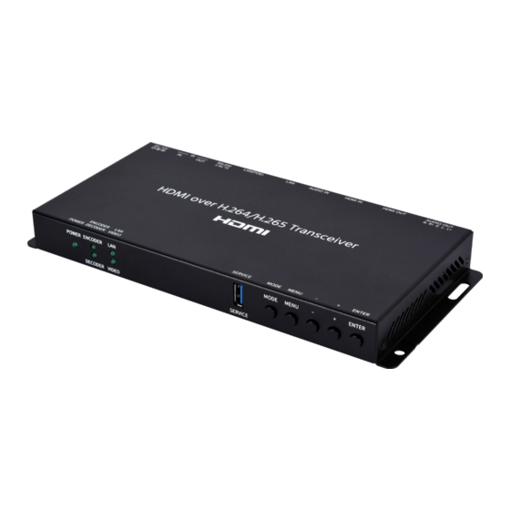
- Page 1 CDPS-P314EDC HDMI over H.264/H.265 Transceiver Operation Manual Operation Manual...
- Page 2 ® registered trademarks of HDMI licensing Administrator, Inc.
- Page 3 DISCLAIMERS The information in this manual has been carefully checked and is believed to be accurate. Cypress Technology assumes no responsibility for any infringements of patents or other rights of third parties which may result from its use. Cypress Technology assumes no responsibility for any inaccuracies that may be contained in this document.
- Page 4 SAFETY PRECAUTIONS Please read all instructions before attempting to unpack, install or operate this equipment and before connecting the power supply. Please keep the following in mind as you unpack and install this equipment: • Always follow basic safety precautions to reduce the risk of fire, electrical shock and injury to persons.
-
Page 5: Table Of Contents
CONTENTS 1. Introduction ............1 2. Applications ............. 1 3. Package Contents ........... 2 4. System Requirements ........2 5. Features............3 6. Operation Controls and Functions ....4 6.1 Front Panel ..........4 6.2 Rear Panel........... 5 6.3 IR Cable Pinouts.......... 6 6.4 RS-232 Pinout and Defaults ...... -
Page 6: Introduction
1. INTRODUCTION As an increasing number of people share videos across the Internet, a simple to configure and easy to use transceiver that supports native H.265/ H.264 encoding and decoding will be indispensable. This HDMI over H.264/ H.265 Transceiver, in Encoder mode, can encode any standard UHD HDMI source and generate a high quality, low latency, video stream for distribution over standard Gigabit Ethernet networks while also supporting archival storage. -
Page 7: Package Contents
3. PACKAGE CONTENTS • 1× HDMI over H.264/H.265 Transceiver • 1× 12V/3A DC Power Adapter (Optional) • 1× Power Cord (Optional) • 1× 5-pin Terminal Block • 1× 3-pin Terminal Block • 1× Shockproof Feet (Set of 4) 4. SYSTEM REQUIREMENTS •... -
Page 8: Features
5. FEATURES • HDMI 2.0 and DVI 1.0 compatible • HDCP 1.x and HDCP 2.2 compliant Note: HDCP encrypted sources cannot be streamed over the Internet or recorded and will be blacked out • 1 HDMI input and 1 HDMI output •... -
Page 9: Operation Controls And Functions
6. OPERATION CONTROLS AND FUNCTIONS 6.1 Front Panel POWER LED: This LED will illuminate to indicate the unit is on and receiving power. ENCODER/DECODER LEDs: These LEDs will illuminate to indicate if the unit is in Encoder or Decoder mode. VIDEO LED: This LED will illuminate when the currently selected video source is connected and active. -
Page 10: Rear Panel
6.2 Rear Panel L+ L- G R+ R- TX RX DC 12V AUDIO OUT HDMI OUT HDMI IN AUDIO IN LAN(POE) RS-232 AUDIO OUT 5-pin Terminal Block: Connect to powered speakers or an amplifier for analog stereo audio output. Note: Only LPCM 2.0 sources are supported. HDMI OUT Port: Connect to an HDMI TV, monitor, or amplifier for digital video and audio output. -
Page 11: Ir Cable Pinouts
6.3 IR Cable Pinouts IR Extender IR Blaster Cable Cable Power Infrared Infrared Power Not Used Ground 6.4 RS-232 Pinout and Defaults Serial Port Default Settings Baud Rate 19200 Data Bits Parity Bits None Stop Bits Flow Control None 3-pin Terminal Block... -
Page 12: Osd Menu
6.5 OSD Menu All functions of this unit can be controlled by using the OSD (On Screen Display) which is activated by pressing the MENU button on the front of the unit. Use the + (PLUS), − (MINUS), and ENTER buttons to navigate the OSD menu. - Page 13 VIDEO 2ND LEVEL 3RD LEVEL STREAMING Decoder Video Source HDMI NATIVE Output Resolution Auto 1280x720p50 1280x720p60 1920x1080p30 1920x1080p50 1920x1080p60 3840x2160p25 3840x2160p30 3840x2160p50 3840x2160p60 COPY SINK HDMI EDID FHD 2Ch UHD 2Ch UHD+ 2Ch User 1) Decoder Video Source: Select the input source, between Streaming or local HDMI, to output to the connected display.
- Page 14 AUDIO 2ND LEVEL 3RD LEVEL HDMI Mute Line Out Mute Line Out Volume 0~100 (80) 1) HDMI Mute: Enable or disable muting the HDMI output’s audio. 2) Line Out Mute: Enable or disable muting the analog audio output. 3) Line Out Volume: Set the volume level of the analog audio output. 2ND LEVEL 3RD LEVEL H Position...
- Page 15 2ND LEVEL 3RD LEVEL Display 1) H/V Position: Set the horizontal and vertical position of the OSD menu. 2) Timer: Set how long to wait before automatically closing the OSD menu if there is no user activity. The timeout can be set to up to 60 seconds, or disabled completely.
- Page 16 ETHERNET 2ND LEVEL 3RD LEVEL 4TH LEVEL [Current IP Address] [Unit’s MAC Address] 1) IP Mode: Set the unit to Static or DHCP mode. When DHCP mode is selected, all IP address information will be assigned automatically by the local DHCP server. When Static is selected, the IP address, netmask and gateway must be set manually using the “Setup Static IP”...
-
Page 17: Webgui Control
6.6 WebGUI Control • Device Discovery Please obtain the “Device Discovery” software from your authorized dealer and save it in a directory where you can easily find it. Connect the unit and your PC/Laptop to the same active network and execute the “Device Discovery”... - Page 18 • WebGUI Overview After connecting to the WebGUI’s address in a web browser, the login screen will appear. Please enter the appropriate user name and password then click “Submit” to log in. Note: The default user name and password is “admin”. On the left side of the browser you will see one of the two following menu tab sets, depending on if the unit is in transmitter or receiver mode, where all primary functions of the unit are controllable via the built in WebGUI.
-
Page 19: Preview Tab
6.6.1 Preview Tab In Encoder mode, this tab provides a limited framerate preview window of the primary video stream channel generated by the unit. At the bottom of the tab a connection address for video stream 1 is displayed in the format: “rtsp:// x.x.x.x/stream”... -
Page 20: System Tab
6.6.2 System Tab This tab provides access to system configuration options including device information and network configuration, firmware update, security configuration, and account configuration. 1) Info: This section provides information and control over the unit’s operational mode, device name, and network configuration. Options for updating the firmware, saving/restoring the unit’s configuration, and performing a factory reset is also provided. - Page 21 Video Output Timing (Decoder Mode Only): Displays the unit’s current output resolution. „ Network: The unit’s IP mode may be switched between Static IP and DHCP. In Static IP mode the IP, netmask and gateway addresses may be manually set. When in DHCP mode, the unit will attempt to connect to a local DHCP server and obtain IP, netmask and gateway addresses automatically.
- Page 22 2) 802.1x Security: This section provides a way to enable network security support for the video streams, if desired. Note: If an incoming video stream has security enabled, all receiving units must be configured to support the same security method as the transmitter.
- Page 23 TLS: After selecting TLS, the following settings must be configured and saved in order to enable TLS authentication on this unit. Press “Save” to save the current configuration. Press “Revert” to undo all unsaved changes made to the current configuration. Press “Test” to test the TLS authentication.
- Page 24 Tunneled TLS: After selecting Tunneled TLS, the following settings must be configured and saved in order to enable TTLS authentication on this unit. Press “Save” to save the current configuration. Press “Revert” to undo all unsaved changes made to the current configuration. Press “Test” to test the TTLS authentication.
- Page 25 3) HTTPS Setting: This section provides a way to enable network security support for the WebGUI connection, if desired. After making changes, press the “Save” button to activate them. Note: Enabling HTTPS support will NOT disable access via normal HTTP. „...
- Page 26 4) Account Config: This section provides control over login authentication and access to the WebGUI itself. „ Authentication Config: Settings related to requiring authentication to connect to the WebGUI. - Authentication: Enable or disable requiring a login to access the WebGUI.
-
Page 27: Settings Tab
6.6.3 Settings Tab This tab provides access to system configuration options including time settings and RS-232/IR routing configuration. 1) Time Setting: This section provides a way to set the system’s time, date, and time zone. The system time can be set manually, or automatically using a defined NTP server. - Page 28 clock running. „ Live Time: Displays how long since the unit was most recently powered on. „ Daylight: Enable or disable the use of Daylight Saving Time (DST) adjustments for the unit’s time. Note: Enabling Daylight Saving Time while outside the configured DST range will result in no change to the current time.
- Page 29 2) RS-232/IR: This section controls the free routing behavior of the IR and RS-232 streams as well as configuring the RS-232 settings. Note: Independent routing control is only available via the optional IP Master Controller hardware. „ IR Setting: Enable or disable the ability to freely route IR signals on this unit.
-
Page 30: Transmitter Tab (Encoder Mode)
6.6.4 Transmitter Tab (Encoder Mode) This tab is only available when the unit is in Encoder mode. This tab provides access to multicast and port configuration, video profile control, service streaming configurations, EDID settings, and Audio routing control. 1) Casting Mode: Set the encoder’s multicast IP configuration for use by decoders in the video wall configuration and the unit’s streaming port. - Page 31 2) Video Profile: This section provides access to the settings which are used when streaming to standard network targets such as transceivers in decoder mode, web browsers or PCs running video software. The Primary and Secondary stream’s settings can be configured here. Pressing the “Save”...
- Page 32 „ Secondary Stream: These are the settings for the alternate, lower resolution/bitrate stream. Encoder Mode: Set the codec to use when transmitting this stream. Maximum Bitrate (kbps): Select the maximum bitrate available for use by the secondary stream. Available bitrate is from 100 to 10000kbps.
- Page 33 3) Streaming: This section provides access to controls for the streaming channel which is used when streaming directly to a streaming service such as YouTube or Facebook. Pressing the “Save” button will store any changes made to these settings. „ Start/Stop: Click on this toggle switch to immediately start or stop streaming to the currently configured streaming target.
- Page 34 4) EDID Setting: This section provides the option of three standard EDIDs, one sink sourced EDID and one customer uploaded EDID that can be assigned to the HDMI input port. „ Input EDID: Use the dropdown to select the EDID to use with the input.
-
Page 35: Receiver Tab (Decoder Mode)
5) Audio Setting: This section provides control over the local HDMI and analog audio output of the unit. „ HDMI Mute: Enable or disable muting the local HDMI output’s audio. „ Analog Mute: Enable or disable muting the local analog audio output. „... - Page 36 Display Mode: Use the dropdown to set the unit’s video output mode. Available options are: Full Screen, Video Wall, Multiview, and Disable. Note: Control over multiviewer mode is only available via the optional IP Master Controller hardware. Resolution: Use the dropdown to select the resolution to use for video output.
- Page 37 to open the file selection window and then select an appropriate EDID file (*.bin format) located on your local PC. After selecting the file, click the “Upload” button to load the firmware into the unit. 2) Audio Setting: This section provides control over the local HDMI and analog audio output of the unit including independent routing selection.
- Page 38 sources will be selected from the currently routed video stream’s encoder. Analog Mute: Enable or disable muting the local analog audio output. Volume: Use the slider to set the volume level of the local analog audio output. The available range is from 0 to 100. Hostname/IP: Type the hostname or IP address of the Encoder to stream audio from.
- Page 39 „ Vertical/Horizontal Monitor Count: Use the dropdowns to select the size of the video wall, measured in number of monitors tall by number of monitors wide. The maximum number of displays in a single video wall is 256 (16×16). Note: It is strongly recommended to use the same make and model for all displays within a video wall to avoid bezel and panel size discrepancies.
-
Page 40: Recording Tab (Encoder Mode)
6.6.6 Recording Tab (Encoder Mode) This tab provides access to the settings and controls for configuring and making a recording of the primary broadcast stream to a local or network storage location. When recording is enabled, the stream is saved as a *.mp4 file, encoded with the same settings as the primary stream, to one of three possible target destinations: USB storage, network storage using NFS, or network storage using CIFS. - Page 41 „ Remote Storage (NAS) NFS: This section provides a way to configure access to a NAS (Network Attached Storage) device using the NFS protocol. Enable/Disable: Enable or disable access to the defined NFS based network storage server. Remote IP: Enter the IP address of the target NFS based NAS device. Folder: Enter a valid share name on the target server.
- Page 42 2) Record Schedule: This section provides a way to enable or disable the scheduled time recording function and configure the times to record. Each hour of each day is divided into two half-hour blocks. Currently selected recording times are indicated by orange blocks. Gray blocks indicate that no recording is currently scheduled.
-
Page 43: Telnet Control
6.7 Telnet Control Before attempting to use Telnet control, please ensure that both the unit and the PC are connected to the same active networks. Start your preferred Telnet/Console client, or use the built in client provided by most modern computer operating systems. After starting the client, connect by using the current IP address of the unit and port 23 (if the communication port number used by the unit has not been changed previously). - Page 44 COMMAND Description and Parameters get command ver Show the unit’s current command version. get mac addr Show the unit’s MAC address. get model name Show the unit’s model name. get model type Show the unit’s product type. Possible response values: [Matrix] [Scaler] [Splitter]...
- Page 45 COMMAND Description and Parameters set system reboot Reboot the unit. set uart 1 reset Reset the unit’s RS-232 settings to the factory defaults. set uart 1 baudrate N1 Set the baud rate of the RS-232 port. Available values for N1: 4800 [4800 baud] 9600...
- Page 46 COMMAND Description and Parameters set uart 1 parity N1 Set the parity of the RS-232 port. Available values for N1: [None] [Odd] [Even] get uart 1 parity Show the current parity setting of the RS-232 port. get webgui username Show the current WebGUI login administrator username. set webgui password N1...
- Page 47 COMMAND Description and Parameters get webgui login timeout Show the current WebGUI inactivity timeout value. set lan 1 ip mode N1 Set the unit’s IP address assignment mode. Available values for N1: STATIC [Static IP mode] DHCP [DHCP mode] get lan 1 ip mode Show the current IP address assignment mode.
- Page 48 COMMAND Description and Parameters get lan 1 static gateway Show the unit’s current static gateway address. set out A route N1 Select the input to be output over HDMI and streamed. Available values for N1: [Streaming input] [HDMI input] get out A route Show the currently selected input.
- Page 49 COMMAND Description and Parameters get out A sync status Show the current sync state of the HDMI output. Possible response values: [No sync] [Sync active] set transceiver device mode N1 Configure the transceiver to behave as either a transmitter or receiver. Available values for N1: [Encoder mode] [Decoder mode]...
- Page 50 COMMAND Description and Parameters set out A osd info display N1 Enable or disable the info OSD for the HDMI output. Available values for N1: [Always off] [Always on] [On for 5 seconds] [On for 10 seconds] get out A osd info display Show the current info OSD state for the HDMI output.
- Page 51 COMMAND Description and Parameters set audio out N1 mute N2 Enable or disable muting the specified audio output. Available values for N1: [HDMI output] [Analog audio output] Available values for N2: [Mute] [Unmute] get audio out N1 mute Show the current mute state of the specified output. Available values for N1: [HDMI output] [Analog audio output]...
- Page 52 COMMAND Description and Parameters set audio out B volume N1 Set the volume level of the analog audio output. N1 = 0-100 [Volume level] get audio out B volume Show the current volume level of the analog audio output. set audio out B volume up Increase the volume level of the analog audio output by 1 unit.
- Page 53 COMMAND Description and Parameters set in 1 edid N1 Set the EDID to use on the HDMI input. Available values for N1: [FHD 2CH] [UHD 2CH] [UHD+ 2CH] [User EDID] [Sink EDID] get in 1 edid Show the EDID currently being used on the HDMI input. get in edid list...
- Page 54 COMMAND Description and Parameters set encoder 1 profile N1 resolution N2 Set the maximum resolution for the specified streaming channel on the encoder. Available values for N1: [Primary channel] [Secondary channel] Available values for N2: [4K (3840×2160)] [1080p (1920×1080)] [720p (1280×720)] [480p (640×480)] get encoder 1 profile N1 resolution...
- Page 55 COMMAND Description and Parameters set encoder 1 profile N1 framerate N2 Set the frame rate for the specified streaming channel on the encoder. Available values for N1: [Primary channel] [Secondary channel] Available values for N2: 1~60 [Frames per second] get encoder 1 profile N1 framerate Show the current frame rate used by the specified streaming channel on the encoder.
- Page 56 COMMAND Description and Parameters set live encode resolution N1 Set the encoding resolution to use with the current live streaming target service. Available values for N1: [1080p (1920×1080)] [720p (1280×720)] [480p (640×480)] get live encode resolution Show the encoding resolution used with the current live streaming target service.
- Page 57 COMMAND Description and Parameters set record mode N1 Start or stop recording video to the currently set target destination. Available values for N1: [Start recording] [Stop recording] get record mode Show the current recording status. set record overwrite N1 Enable or disable the record overwrite function. Available values for N1: [Enable overwrite] [Disable overwrite]...
- Page 58 COMMAND Description and Parameters set record profile path N1 Set the source stream profile to use when recording video. Available values for N1: [Primary stream] [Secondary stream] get record profile path Show the currently selected source stream profile used when recording video.
-
Page 59: Connection Diagram
7. CONNECTION DIAGRAM PC/Laptop PC/Laptop PC/Laptop PC/Laptop HDMI In HDMI In HDMI In HDMI In L+ L- G R+ R- TX RX L+ L- G R+ R- TX RX DC 12V DC 12V AUDIO OUT HDMI OUT HDMI IN AUDIO IN LAN(POE) RS-232 AUDIO OUT... -
Page 60: Specifications
8. SPECIFICATIONS 8.1 Technical Specifications HDMI Bandwidth 18Gbps Ethernet Bandwidth 1Gbps Streaming Input Max 3840x2160@60Hz (YUV, 4:4:4) Streaming Output Max 3840x2160@30Hz (YUV, 4:4:4) Input Ports 1×HDMI (Type-A) 1×Stereo Audio (3.5mm) Output Ports 1×HDMI (Type-A) 1×Stereo Audio (5-pin Terminal Block) Pass-through Ports 1×IR Extender (3.5mm) 1×IR Blaster (3.5mm) 1×RS-232 (DE-9) -
Page 61: Video Specifications
8.2 Video Specifications Input Output Supported Resolutions (Hz) HDMI Streaming HDMI Streaming 720×400p@70/85 640×480p@60/72/75/85 720×480i@60 720×480p@60 720×576i@50 720×576p@50 ... - Page 62 Input Output Supported Resolutions (Hz) HDMI Streaming HDMI Streaming 2560×1440p@60RB 2560×1600p@60RB 2048×1080p@24/25/30 2048×1080p@50/60 3840×2160p@24/25/30 3840×2160p@50/60 (4:2:0) 3840×2160p@24, HDR10 ...
-
Page 63: Audio Specifications
8.3 Audio Specifications 8.3.1 Digital Audio HDMI Input / Output LPCM Max Channels 2 Channels Sampling Rate (kHz) 32, 44.1, 48, 88.2, 96, 176.4, 192 Bitstream Supported Formats None 8.3.2 Analog Audio Analog Input Max Audio Level 2Vrms Impedance 10kΩ Type Unbalanced Analog Output... -
Page 64: Cable Specifications
8.4 Cable Specifications 1080p 4K30 4K60 (4:4:4) (4:4:4) Cable Length 8-bit 12-bit 8-bit 8-bit High Speed HDMI Cable HDMI Input HDMI Output Bandwidth Category Examples: • 1080p (FHD Video) - Up to 1080p@60Hz, 12-bit color - Data rates lower than 5.3Gbps or below 225MHz TMDS clock •... -
Page 65: Acronyms
9. ACRONYMS ACRONYM COMPLETE TERM Analog-to-Digital Converter ASCII American Standard Code for Information Interchange AVoIP Audio/Video over IP Cat.5e Enhanced Category 5 cable Cat.6 Category 6 cable Cat.6A Augmented Category 6 cable Cat.7 Category 7 cable Consumer Electronics Control Command-Line Interface Digital-to-Analog Converter Decibel DHCP... - Page 66 ACRONYM COMPLETE TERM Media Access Control Megahertz On-Screen Display Powered Device Picture in Picture Power over Ethernet Picture outside of Picture Signal-to-Noise Ratio Transmission Control Protocol THD+N Total Harmonic Distortion plus Noise TMDS Transition-Minimized Differential Signaling 4K UHD 4K Ultra-High-Definition (10.2Gbps max) 4K UHD 4K Ultra-High-Definition (18Gbps max) UHDTV...
- Page 68 CYPRESS TECHNOLOGY CO., LTD. www.cypress.com.tw...
Need help?
Do you have a question about the CDPS-P314EDC and is the answer not in the manual?
Questions and answers