
Subscribe to Our Youtube Channel
Related Manuals for Teknik Hudson 5425829


Summary of Contents for Teknik Hudson 5425829
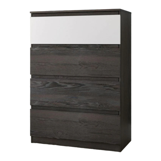
- Page 1 Teknik www.teknikoffice.co.uk You won't lose your shirt with this one. Hudson 4-Drawer Chest NOTE: THIS INSTRUCTION BOOKLET CONTAINS IMPORTANT SAFETY INFORMATION. Model 5425829 PLEASE READ AND KEEP FOR FUTURE REFERENCE.
- Page 2 Table of Contents Assembly Tools Required Part Identifi cation No. 2 Phillips Screwdriver Tip Shown Actual Size Hardware Identifi cation Assembly Steps 5-21 Français 22-24 Electric drill with 1/8" bit (ONLY in indicated step) Español 25-28 Safety 29-30 Warranty Page 2...
-
Page 3: Part Identification
Now you know Part Identifi cation our ABCs. å While not all parts are labeled, some of the parts will have a label or an inked letter on the edge to help distinguish similar parts from each other. Use this part identifi cation to help identify similar parts. LEFT END (1) DRAWER FRONT (3) UPPER BACK (1) -
Page 4: Hardware Identification
Hardware Identifi cation å Screws are shown actual size. You may receive extra hardware with your unit. 35AA UNIVERSAL CABINET RAIL - 8 35AC DRAWER RIGHT - 4 35AD DRAWER LEFT - 4 LARGE HIDDEN SMALL HIDDEN CAM SCREW - 37 CAM - 17 CAM - 20 LARGE WOOD... - Page 5 Step 1 Assemble your unit on a carpeted fl oor or on the empty å VIEW THE DRAWER GLIDE VIDEO carton to avoid scratching your unit or the fl oor. Fasten the UNIVERSAL CABINET RAILS* (35AA) to the å ENDS (A and B). Use sixteen BLACK 3/8" FLAT HEAD SCREWS (10) through holes #1 and #3.
- Page 6 Hardware Usage Guide HOW TO USE A HIDDEN CAM & CAM SCREW OR CAM DOWEL NOTE: Various CAM SCREWS or a CAM DOWEL may be used. Turn the CAM SCREW or gently tap the CAM DOWEL until the shoulder is against the surface of the part.
- Page 7 Step 2 Push four LARGE HIDDEN CAMS (1) into the ENDS (A and B). å Turn twelve CAM SCREWS (3) into the exact holes shown in å Some assembly the ENDS (A and B). (and snacks) required. Then, insert twenty-two LARGE WOOD DOWELS (4) into the å...
- Page 8 Step 3 Push one LARGE HIDDEN CAM (1) into the LOWER BACK (P) as shown. å Turn one CAM SCREW (3) into the BOTTOM (D). å Insert two LARGE WOOD DOWELS (4) into the BOTTOM (D). å Fasten the LOWER BACK (P) to the BOTTOM (D). Tighten one HIDDEN CAM. å...
- Page 9 Step 4 Insert six LARGE WOOD DOWELS (4) into the long edges of the å CENTER BACK (O). Insert the LARGE WOOD DOWELS in the CENTER BACK (O) into å the BACKS (N and P) so the BACKS are all connected. (6 used) Notch Page 9...
- Page 10 Step 5 Push fi ve LARGE HIDDEN CAMS (1) into the BOTTOM (D) å and BACKS (N, O, and P). Fasten the RIGHT END (B) to the BOTTOM (D) and å BACKS (N, O, and P). Tighten fi ve HIDDEN CAMS. NOTE: Be sure the WOOD DOWELS in the RIGHT END insert å...
-
Page 11: Hidden Cam
Step 6 Push two LARGE HIDDEN CAMS (1) into the BRACE (F). å Fasten the BRACE (F) to the RIGHT END (B). Tighten one å HIDDEN CAM. NOTE: Be sure the WOOD DOWEL in the RIGHT END å inserts into the BRACE. Arrow Arrow Finished edge... - Page 12 Step 7 Push fi ve LARGE HIDDEN CAMS (1) into the BOTTOM (D) å and BACKS (N, O, and P). Fasten the LEFT END (A) to the BOTTOM (D), BRACE (F), and å BACKS (N, O, and P). Tighten six HIDDEN CAMS. NOTE: Be sure the WOOD DOWELS in the LEFT END insert into å...
- Page 13 Step 8 Fasten the BALLAST (Q) to the BOTTOM (D). Use four å SILVER 1-1/8" FLAT HEAD SCREWS (8). Now might be a good time to refresh NOTE: You should start each SCREW a few turns before å your drink. completely tightening any of them.
- Page 14 Step 9 Turn four CAM SCREWS (3) into the TOP (C). å Insert six LARGE WOOD DOWELS (4) into the TOP (C). å Open the FURNITURE TIPPING RESTRAINT KIT (98) å and fasten the SAFETY STRAP to the TOP (C). Use the provided short screw.
- Page 15 Step 10 Fasten the TOP (C) to the ENDS (A and B). Tighten four å HIDDEN CAMS. NOTE: Be sure the WOOD DOWELS in the TOP insert å into the ENDS (A and B) and UPPER BACK (N). NOTE: The SAFETY STRAP should go through the notch å...
- Page 16 Step 11 Carefully stand your unit upright in its fi nal location. We å recommend using the SAFETY STRAP for added stability. Locate the center of a stud in your wall near your unit and å mark it with a pencil just below the top surface of your unit so the SAFETY STRAP will not be visible.
- Page 17 Step 12 Insert four SMALL WOOD DOWELS (5) into the center holes in å the short edges of the DRAWER BACK (J). Fasten the DRAWER SIDES (H and S) to the DRAWER BACK (J). å Use four SILVER 1-1/2" FLAT HEAD SCREWS (7). Slide a DRAWER BOTTOM (K) into the grooves in the DRAWER å...
- Page 18 Step 13 Fasten a DRAWER FRONT MOLDING (M) to the WHITE å DRAWER FRONT (R). Use three BLACK 3/4" FLAT If you're doing this to HEAD SCREWS (9). help a friend, don't leave without a bite. Turn fi ve CAM SCREWS (3) into the exact holes shown å...
-
Page 19: Flat Head Screw
Step 14 Push fi ve SMALL HIDDEN CAMS (2) into the DRAWER SIDES (H and S) and DRAWER BRACE (L). å Fasten the WHITE DRAWER FRONT (R) to the DRAWER SIDES (H and S) and DRAWER BRACE (L). Tighten fi ve å... - Page 20 Step 15 Fasten the DRAWER RIGHT (35AC) to the RIGHT å DRAWER SIDE (S) and the DRAWER LEFT (35AD) to the LEFT DRAWER SIDE (H). Use four BLACK 3/8" FLAT HEAD SCREWS (10) through holes #1 and #2. NOTE: The glides are not intended to rotate. å...
- Page 21 Step 16 Peel the APPLIQUES from the APPLIQUE CARDS (6) and stick them onto each visible HIDDEN CAM in å the DRAWER SIDES. To insert the drawers into your unit, tip the front of the drawer down and drop the glides on the drawer å...
- Page 22 WARNING Please use your furniture correctly and safely. Improper use can cause safety hazards, or damage to your furniture or household items. Carefully read the following safety information. Death or serious injury may occur when children climb on furniture. A remote control, toys or other items placed on the furniture may encourage a child to climb on the furniture which could cause it to tip-over and result in serious injury or death.
Need help?
Do you have a question about the Hudson 5425829 and is the answer not in the manual?
Questions and answers