DMP Electronics 734 Installation Sheet
Wiegand interface module
Hide thumbs
Also See for 734:
- Installation and programming manual (44 pages) ,
- Quick start manual (2 pages) ,
- Installation and programming manual (40 pages)
Table of Contents
Advertisement
Quick Links
Description
The 734 Wiegand Interface Module allows you to use the powerful built-in access control capability of DMP Command
Processor™ Panels. The XRSuper6, XR20, XR40, XR100, XR500 Series and XR2500F panels provide system door
control, arming, and disarming using proximity or mag-stripe devices. The 734 Module easily connects to the keypad
bus of any of the panels listed above.
The 734 operates on 12 VDC input and provides four power-limited programmable zones. Zones 1, 2 and 3 can be
programmed for a variety of burglary or access control applications. Zone 4 is a Class B, Style A circuit that can be
programmed as a fire zone. Additionally, the module supplies a Form C Single Pole Double Throw (SPDT) Door Strike
relay, built-in piezo with remote annunciation output, data to panel LED, and a 4-position terminal for connecting
one or more external Wiegand format readers.
The Form C relay draws up to 35mA of current and its contacts are rated for 10 Amps at 12 VDC. Refer to the
NC/C/NO (Dry Contact Relay) and the Isolation Relay sections in this document for more information.
Access Control
The 734 module allows users to present an access credential, such as a card or keyfob, to a Wiegand reader. The
reader then sends the Wiegand input to the 734 module that reads the user code and verifies its authority with the
panel. After verifying the code has the proper authority, the 734 module powers its on-board Form C relay releasing
a door strike or magnetic lock.
Enroll Users
DMP 793 Security Command or 7063, 7063A, 7073, 7073A, 7163 or 7173 Thinline LCD keypads can be used to enroll
users. Remote Link™ or System Link™ with an Admin Reader can also be used to quickly enroll users in the system.
The 734 cannot be used to enroll users.
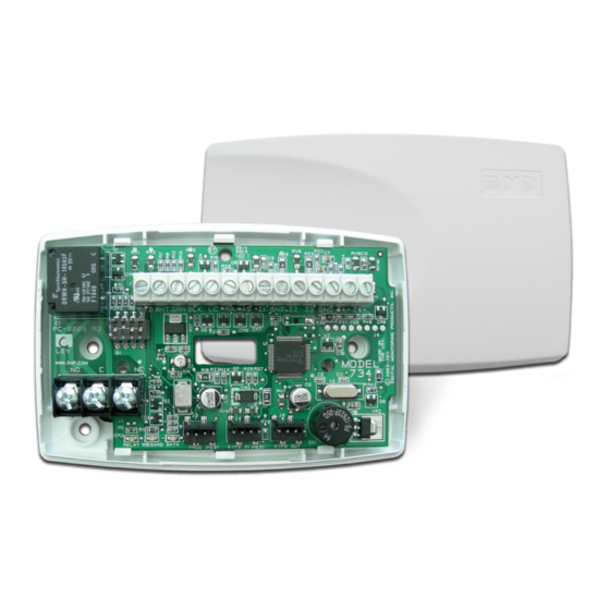
Mount the 734 to Walls
The 734 ships installed in a decorative, high-impact plastic case that mounts directly to walls, backboards, or other
flat surfaces. For easy installation, the 734 housing back and both ends have wire entrances. The bottom half of the
plastic case contains two screw holes for mounting the case on single-gang switch boxes. It is recommended that
you mount the 734 near the protected door.
Mount the 734 in Panel Enclosures
You can also install the 734 in a panel enclosure using the standard 3-hole mounting configuration.
1. Mount the plastic standoffs to the enclosure using the three included Phillips head screws.
2. Insert the screws through the holes on the enclosure exterior side and into the plastic standoffs which mount on
the enclosure inside. Tighten the screws into place.
3. After tightening and securing the standoffs onto the enclosure, snap the 734 onto the standoffs.
Install the 333 Suppressor
One Model 333 Suppressor is included with the 734 module. Install the suppressor across the 734 Common (C) and
Normally Open (NO) or Normally Closed (NC) terminals on J1.
If the device being controlled by the relay is connected to the NO and C terminals, install the suppressor on the NO
and C terminals. Conversely, if the device is connected to the NC and C terminals, install the 333 Suppressor on NC
and C terminals.
The suppressor wire is non-polarized. Install the suppressor as shown in Figure 1.
Inst alla tIon sheet
734 Wiegand Interface Module
734 Interface Module
NO
C
NC
J1
RED
YEL
GRN
PROG
RELAY
WIEGAND
DATA
ON
READ LED
XMT LED
Model 333 Suppressor
Wire the Suppressor to the Common and Normally Open or Normally
Closed depending upon which terminals are used for the device.
Figure 1: Model 333 Installation on the 734 Module
J2
J4
J5
Piezo
+
RED
RED
KYPD IN
KYPD OUT
–
Advertisement
Table of Contents

Subscribe to Our Youtube Channel
Related Manuals for DMP Electronics 734


Summary of Contents for DMP Electronics 734
- Page 1 Access Control The 734 module allows users to present an access credential, such as a card or keyfob, to a Wiegand reader. The reader then sends the Wiegand input to the 734 module that reads the user code and verifies its authority with the panel.
- Page 2 1 2 3 4 Figure 2: 734 Addresses 734 Module Wiring The 734 connects to the keypad data bus and a Wiegand format reader. Refer to Figures 3, 4, and 5 and the instructions in this guide for proper wiring. Remote LED Control...
- Page 3 12 VDC Power You can power the 734 module from a 12 VDC power source. The 12 VDC power can be provided by the panel or from a separate listed burglary and fire alarm auxiliary power supply. Do not ground the power supply to the 734 or Command Processor™...
- Page 4 Magnetic Lock and Door Strike Wiring You can control door strikes and magnetic locks by using the Form C relay on the 734 module. Use an additional power supply to power door strikes and magnetic locks. Refer to the following figures for wiring information.
- Page 5 After you have properly wired the 734 interface module, connect the 32-character LCD keypad to the 734 following the steps below: 1. Connect the standard model 330 4-wire programming harness to the 4-pin J2 header on the 734 module. Be sure to match the module Red pin and harness Red wire.
-
Page 6: Activate Zone 3 Request To Exit
The 734 module provides a shunt-only option for REX on Zone 3. When Zone 3 opens from a normal state, only a Soft-Shunt occurs: the on-board relay does not activate. This shunt- only option uses two methods of REX. -
Page 7: Card Options
Select key under DMP. Press the COMMAND key to display REQUIRE SITE CODE. Default is DMP. Note: When set to DMP, the 734 converts the last 17 bits of the 26-bit data string into a 5-digit number. -
Page 8: Require Site Code
USEr CoDE DigiTS: The 734 module recognizes user codes from four to eight digits in length. Press any top row Select key to enter a user code digit length between 4-8 digits. This number must match the user code number length being used by the panel. Default is 5. -
Page 9: Degraded Mode
The REMOVE KEYPAD option continually displays with no time out while the keypad remains connected to the 734 module after programming is finished. After five seconds the 734 module piezo continually sounds if the keypad remains connected and programming is finished. -
Page 10: Specifications
ULC Commercial Burglary (XR100/XR500 Series Panels) When using the zones of the 734 in a listed application, place the module in a listed enclosure and connect a DMP Model 307 Clip-on Tamper Switch to the enclosure programmed as a 24-Hour zone.
Need help?
Do you have a question about the 734 and is the answer not in the manual?
Questions and answers