Table of Contents
Advertisement
Quick Links
Advertisement
Table of Contents

Subscribe to Our Youtube Channel
Related Manuals for CHART ULTRADOSER 500S


Summary of Contents for CHART ULTRADOSER 500S
- Page 1 ® ULTRADOSER 500S Dosing System USER MANUAL...
-
Page 2: Table Of Contents
Safety ...................................... 5 Safety Bulletin ........................6 ® Receiving Your UltraDoser 500S LN Dosing System ......................8 Unpacking the UltraDoser 500S System ........................8 ® UltraDoser 500S LN Dosing System Overview and Utilities ....................9 Product Specifications ......................9 Utility Requirements ......................9 ®... -
Page 3: Introduction
Chart’s service team at +1 408.371.4932. Service Chart’s UltraDoser 500S Dosing System has been designed for years of safe and dependable operation. In the event service is required, please contact Chart at: Chart Inc. - Page 4 This manual is provided by Chart to its customers as a courtesy and, except as expressly provided in this manual, CHART MAKES NO WARRANTIES, EXPRESS OR IMPLIED, REGARDING THE CONTENTS IN THIS MANUAL.
-
Page 5: Safety
LN doses before sealing. WARNING! If you are at all unsure of how to safely work on this system, STOP and contact Chart immediately at +1 408.371.4932. CAUTION: As with any cryogenic system, it should be observed that any non-insulated piping can get extremely cold and should not be touched by exposed skin. -
Page 6: Safety Bulletin
WARNING! Accidental contact of liquid gases with skin or eyes may cause a freezing injury similar to a burn. Handle liquid so that it will not splash or spill. Protect your eyes and cover skin where the possibility of contact with liquid, cold pipes and equipment, or cold gas exists. - Page 7 Nitrogen Nitrogen (an inert gas) is a simple asphyxiate. It will not support or sustain life and can produce immediate hazardous conditions through the displacement of oxygen. Under high pressure these gases may produce unconsciousness even though an adequate oxygen supply, sufficient for life, is detected. Nitrogen vapors in air dilute the concentration of oxygen necessary to support or sustain life.
-
Page 8: Receiving Your Ultradoser 500S Ln Dosing System
The UltraDoser 500S system is designed for variable speed filling lines up to 500 bottles (or containers) per minute. If set up properly, the UltraDoser 500S system will accommodate for any changes in line speed up to 500 bottlers (or containers). -
Page 9: Ultradoser ® 500S Ln 2 Dosing System Overview And Utilities
Portable Dura-Cyl Liquid Cylinder – 22 psi (1.5 bar) Liquid Nitrogen: House System (with Chart Phase Separator) – 100 psi (6.9 bar) Maximum flow rate 15 gallons (56 liters) per hour Gaseous Nitrogen: 60 to 100 psi (4.1 to 6.9 bar) 10 SCFH gas per 100 bottles (or containers) per minute www.chartdosers.com... -
Page 10: Ultradoser ® Ln 2 Dosing System Body Dimensions
® ® Note: Mounting bracket can be mounted at 90° intervals around the central axis of the UltraDoser body. See page 16 for additional information. *Shown with Standard Head www.chartdosers.com PN 15920 Page 10 of 43... -
Page 11: Ultradoser ® 500S Ln 2 Dosing System Components
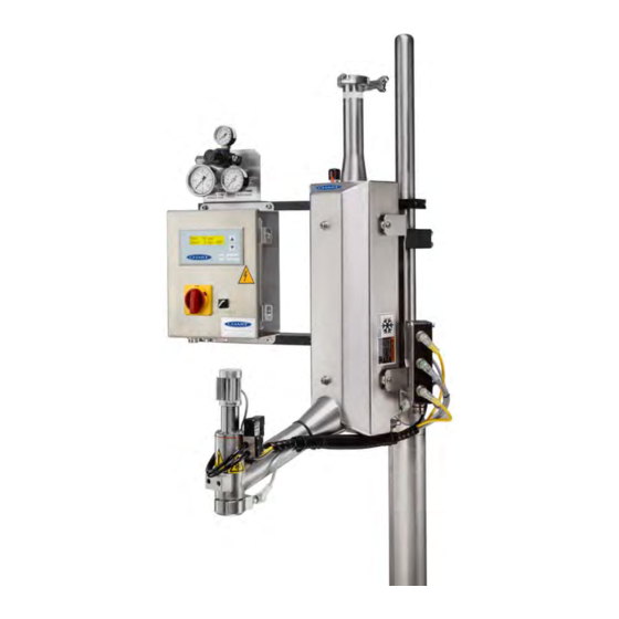
® ® Standard Components (Front View) UltraDoser Body The stainless steel vacuum insulated reservoir provides a working supply of LN for dosing operations from your liquid nitrogen supply. Dosing Valve Assembly The dosing valve assembly contains the solenoid coil, the electromagnetic core with the valve stem, the return spring and the sealed valve housing. - Page 12 The UltraDoser unit is supplied with a mounting bracket assembly. The assembly consists of the bracket attaching to the UltraDoser unit and two clamps. These clamps are designed to fit on Chart’s support stand or 1- 1/2” stainless steel rod. The bracket can be mounted in 3 positions. See page 16 for additional information.
-
Page 13: Standard Components (Back View)
Standard Components (Back View) SRV / Drain Plug ® A 50 psi SRV / drain plug are located on the back of the UltraDoser Dosing System unit. When removed, this allows the LN to drain from the UltraDoser body. The 50 psi safety relief valve (SRV) is provided to protect the unit against over pressurization. If the pressure inside the unit reaches 50 psi or greater, the safety relief valve will vent excess pressure. -
Page 14: Principles Of Liquid Nitrogen (Ln ) Dosing
Pure Liquid at the Dosing Head Pure liquid (i.e. liquid with no gas pockets) must be instantaneously available at the dosing head. Chart has a unique internal design that ensures the continual availability of pure liquid at the dosing head. -
Page 15: Installation
This stand can be utilized in almost all installations. If the Chart stand cannot be used in your installation, fabricating one with 1½”diameter rod or round bar will make installation of the UltraDoser 500S system simpler. The following instructions will assume installation of Chart’s prefabricated support stand (Figure 4). -
Page 16: Mounting The Ultradoser Ln Dosing System Unit
® Mounting the UltraDoser Dosing System Unit Once the stand is installed, mount the UltraDoser unit on the stand using the supplied mounting bracket. www.chartdosers.com PN 15920 Page 16 of 43... -
Page 17: Connecting The Distribution Block
Connecting the Distribution Block The distribution block houses the electrical connectors and wiring interface between the operating parts of the ® UltraDoser Dosing System unit and the 500S controller. There are five connections on the distribution block: Vent Heater (D-1) Provides +24VDC power to the vent heater. -
Page 18: Installing The Nozzle
Three nozzles are supplied with the UltraDoser 500S LN Dosing System – 0.040”, 0.050”, and 0.060”. Custom sizes may be ordered from Chart. 1. Remove the dosing head heater. 2. Select a nozzle. 3. Insert the nozzle into the nozzle tool, threads out (Image 1). -
Page 19: Installing The Container Sensor
Installing the Container Sensor The container sensor must be a PNP type sensor and is used to detect if containers are present on the line. Chart ® provides a PNP 18mm ultrasonic sensor with the UltraDoser 500S LN Dosing System. Ideal container sensor placement is about four (4) to six (6) pockets from the dosing head. -
Page 20: Installing The 500S Controller
Installing the 500S Controller Locate the ideal location for the 500S controller. Brackets can be supplied to mount the controller on the Chart prefabricated support stand or 1½”diameter rod or round bar . If Chart’s prefabricated brackets are not utilized, the controller’s mounting tabs can be utilized. - Page 21 The bottom of the 500S controller (image below) is the electrical “hub”. Input Power (J-1) The 500S controller power cable (6ft) is connected to the 500S controller at port J-1. Interface Connection (J-2) The 500S controller I/O (input/output) cable, a component of the distribution block, is connected to the 500S controller at port J-2.
-
Page 22: 500S Controller Adjustments
www.chartdosers.com PN 15920 Page 22 of 43... -
Page 23: Home Screen
The 500S controller dictates the dosing operation of the system. The controller allows the system to operate in either a “Fixed Delay” or a “Speed Compensation” mode. In Fixed Delay mode, the operator inputs the “Dose Time” and the “Fixed Speed Mode Delay”. When the system detects a bottle (or container), the UltraDoser will dose per the dose time after the fixed speed mode delay time passes. -
Page 24: Alarm Screen
Alarm Screen The software alerts the user for the following reasons: 1. If it detects speed sensor failure after a container has been detected (if in Speed Compensated mode). 2. The dosing valve has not been activated after a container has been detected. The alert will appear as a flashing triangle on the Home screen (image below). -
Page 25: Fixed Delay Mode (Fxdd)
Fixed Delay Mode (FXDD) In Fixed Delay mode, the operator inputs the “Dose Time” and the “Fixed Speed Mode Delay”. When the system detects a bottle (or container), the UltraDoser will dose per the dose time after the fixed speed mode delay time passes. - Page 26 5. Use the arrow key ▲ to go to the Fixed Speed Mode Delay screen (image below). Press ENTER to highlight the digit before ‘msec’. 6. Use the arrow key ▲ or ▼ to change the value. Press ENTER when the desired value is shown; range is 1 to 5000 milliseconds.
-
Page 27: 500S Controller Set-Up Verification
8. Use the arrow key ▲ or ▼ to change the value. Press ENTER when the desired value is shown; range is 15 to 1000 milliseconds. The dose time is now set. 9. On the front of the 500S controller box, place the Dose Enable switch in the enable mode ‘I’. 500S Controller Set-up Verification Send a bottle (or container) down the filling line. -
Page 28: Speed Compensated Mode (Scmp)
Speed Compensated Mode (SCMP) In Speed Compensation mode, the 500S controller automatically adjusts the time delay from the time the ® UltraDoser Dosing System senses the bottle (or container) to when it doses based on the speed of the line. The operator must enter several parameters and install a container sensor and a speed sensor (see page 19 for additional information). - Page 29 6. Use the arrow key ▲ or ▼ to change the value to ‘0’. 7. Use the arrow key ▲ or ▼ to go to the Distance Between Container Centers screen (image below). Press ENTER to highlight the value. IMPORTANT: This measurement is the distance between containers centerline to container centerline (in mm or in).
- Page 30 9. Use the arrow key ▲ or ▼ to go to the Container Center to Dose Center Distance screen (image below). Press ENTER to highlight the value. IMPORTANT: This measurement is the distance between the container sensor and the dosing head nozzle (in mm or in).
- Page 31 11. Use the arrow key ▲ or ▼ to go to the Speed Pulses per Container screen (image below). Press ENTER to highlight the value. IMPORTANT: This is a critical parameter of the system and care should be taken to input the correct value. The number of pulses does not have to be a whole number.
- Page 32 13. Use the arrow key ▲ or ▼ to go to the Dose Time screen (image below). Press ENTER to highlight the value. ® IMPORTANT: The Dose Time setting controls the amount of time (in milliseconds) that the UltraDoser Dosing System dispenses liquid nitrogen. The amount of liquid nitrogen inside a container depends on many variables including the position of the dosing head relative to the capper, the size of the dosing nozzle, the temperature of the container contents, fill levels and head space.
-
Page 33: 500S Controller Set-Up Verification
System Information Screen This System Information screen (image below) shows the 500S controller’s software version. This screen would only be accessed for upgrade or troubleshooting purposes. Contact Chart service at +1 408.371.4932 if access to this screen is necessary. www.chartdosers.com... -
Page 34: Advanced Settings (System Response Time)
Advanced Settings (System Response Time) The System Response Time is an adjustment that is used to make small adjustments to valve timing. It may be required when the normal setup does not correctly dose bottles (or containers). This feature is intended to compensate when the dosing head is greater than 3/4 inch from the bottle (or container) or if the pneumatic pressure (GN ) is near the operational limits of the system. -
Page 35: Daily Operating Procedures
Purging with Gaseous Nitrogen The UltraDoser unit must only be purged with gaseous nitrogen. Chart recommends the UltraDoser unit be purged when not in use. However, this may not be practical for all operators. At a minimum, the UltraDoser unit should be purged to eliminate any water that may be inside the unit after installation and prior to startup. - Page 36 IMPORTANT: The UltraDoser 500S system will continue to dose properly until the liquid level inside the UltraDoser unit runs low. This feature gives the operator a reasonable window in which to change out the Dura- Cyl cylinder without disrupting the production operation.
-
Page 37: Ultradoser ® Ln 2 Dosing System Service And Maintenance
® ® Nozzle Change Out Procedure 1. Remove the dosing head heater. 2. Insert the nozzle tool into the nozzle area until the tool connects with the nozzle (Image 1). 3. Remove the nozzle with the driver in a counter-clockwise direction. Remove. 4. -
Page 38: Nozzle Cleaning Procedure
Dosing System with Gaseous Nitrogen The UltraDoser unit must only be purged with gaseous nitrogen. Chart recommends the UltraDoser unit be purged when not in use. However, this may not be practical for all operators. At a minimum, the UltraDoser unit should be purged to eliminate any water that may be inside the unit after installation and prior to startup. -
Page 39: Ultradoser ® 500S Ln 2 Dosing System Replacement Parts
® ® Refer to page 11 and 13 for location of most replacement parts on the UltraDoser 500S system. Part Description Part Number Injection Unit Spare Parts Kit (Standard Head) Includes PNs: 102, 103, 104, 105C, 106C, 141, 362, and 535... -
Page 40: General Troubleshooting
Below are a few general troubleshooting guidelines. If after reading this section, the condition does not change or the condition is not covered in this section, please contact Chart’s service team at +1 408.371.4932. Condition: The safety relief valve is venting. - Page 41 Condition: No liquid from the dosing head. Possible Causes Actions There is insufficient liquid inside the UltraDoser Open the valve (counter-clockwise direction) on ® unit. the Dura-Cyl Liquid Cylinder. The unit is disabled. Switch the Dose Enable switch to the “I” position. ...
-
Page 42: 500S Controller Wiring Diagram
www.chartdosers.com PN 15920 Page 42 of 43... -
Page 43: Warranty
Dosing Systems”) from Chart Inc. ("Chart") to the purchaser are subject to all applicable Chart standard terms and conditions in effect at the time of sale, unless otherwise agreed in writing by an authorized representative of Chart. In addition to the warranty stated in Chart’s Standard Terms and Conditions of Sale, Chart warrants to the original purchaser of Chart manufactured...
Need help?
Do you have a question about the ULTRADOSER 500S and is the answer not in the manual?
Questions and answers