
Subscribe to Our Youtube Channel
Related Manuals for Nagano Keiki EJ15


Summary of Contents for Nagano Keiki EJ15
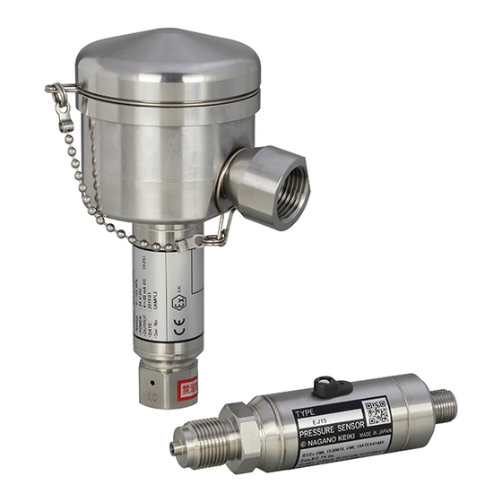
- Page 1 User's Manual EJ15 Intrinsically Safe Pressure Sensor for High Pressure Hydrogen Application (EJ15-□□H)...
-
Page 2: For Proper And Safe Use
FOR PROPER AND SAFE USE Thank you for purchasing the EJ15 intrinsically safe pressure sensor for high-pressure hydrogen application. To use this product properly and safely, read this user's manual carefully. This pressure sensor has passed the type approval test in compliance with IECEx for intrinsically safe construction, which can be used even in Zone 0 areas where Explosive Gases are present at all times. -
Page 3: Precautions For Handling Product
*4 Only inspect this product in the Hazardous Area by visual inspection. Other maintenance work should be performed in a "Non-hazardous Area" and never in the Hazardous Area. Avoid electrostatic charging. When cleaning the product, use a soft cloth containing water. TY-EJ15-003A Rev.2... - Page 4 Disassembly or modification of the product on your own may cause failures. * These precautions are selected from our common safety precautions for all products that correspond to the EJ15 pressure sensor. EJ15-specific precautions are further described in detail in the following sections. TY-EJ15-003A Rev.2...
-
Page 5: Table Of Contents
11. MAINTENANCE ............... 32 ■ 11.1 Periodical Check-up ................32 ■ 11.2 Zeroing ....................32 12. PRODUCT WARRANTY AND EXPORT ADMINISTRATION REGULATIONS ..............34 ■ 12.1 Product Warranty ................... 34 ■ 12.2 Export Administration Regulations ............34 13. OTHER ................34 TY-EJ15-003A Rev.2... -
Page 6: Introduction
DC current output of 4 to 20mA DC. Regulated Power (+) circuit Output Amplifier circuit circuit Detector Power (-) < Fig. 2-1 Block Diagram (4 to 20mA DC/ 2-wire system) > TY-EJ15-003A Rev.2... -
Page 7: Specifications
M12 connector type: 150g approx. (excluding cables) (This will vary depending on the thread type) Mass Terminal box type: 450g approx. (excluding cables) (This will vary depending on the thread type) RoHS compliance conforms to the RoHS Directive < Table 3-1 > TY-EJ15-003A Rev.2... -
Page 8: Intrinsically Safe Specification
10 minutes. Effects of continuous over-pressure are not guaranteed. *2 The formula showing the load resistance refers to the specification of the EJ15 alone, and it will actually depends on the combination with the safety barrier. - Page 9 The following table shows the recommended insulated barriers (safety barriers) to be used with the EJ15 pressure sensor. The insulation barrier does not require grounding regulated for the intrinsically safe construction as it is isolated from the Intrinsically Safe Circuit.
-
Page 10: Dimensions
4. DIMENSIONS ■ 4.1 External Dimensions (Typical) M12 Connector Terminal Box * SUS316L fitting will be printed as “LC” on the hexagon part. < Figure 4-1 > TY-EJ15-003A Rev.2... -
Page 11: Transportation And Unpacking
Do not insert a wire into the pressure inlet. Otherwise, the diaphragm will be damaged and the correct operation will not be obtained. Never pull or bend the cable. Also, during wiring, be careful not to subject the product to the cable weight. TY-EJ15-003A Rev.2... - Page 12 Install the EJ15 during piping so that it is grounded from the main body (fitting) as it is required to do so. (For the terminal box type, the grounding from the EJ15 body can also be obtained from the M4 screw portion provided on the outer terminal box).
-
Page 13: Mounting Direction
< Figure 6-2 Recommended mounting direction for terminal box type > Mount the terminal box type with the terminal box facing up as shown in Figure 6-2. When mounting the product sideways, make sure that the terminal port faces downward. TY-EJ15-003A Rev.2... -
Page 14: Safety Barrier
If the cable capacitance and inductance values that are determined based on the cable size and cable length exceeds the rated value indicated on the barrier minus the Li and Ci values of the EJ15, the certification of the intrinsically safe certification will be invalid. -
Page 15: Wiring And Connection
(or a shielded wire if grounding from the pipe (EJ15 body) is unavailable), outside diameter matching the cable gland size, and the lead wire with a conductor cross-sectional area (core wire) matching the crimp terminal. - Page 16 (5) Use R1.25-3.5 or equivalent (JIS C 2805) crimp terminal for M3.5. < Figure 7-1 > *1 Install the EJ15 during piping so that it is grounded from the main body (fitting) as it is required to do so in principle (For the terminal box type, the grounding from the EJ15 body can also be obtained from the M4 screw portion provided on the outer terminal box).
- Page 17 Also, do not seal the cable ends with taping or adhesive during wiring. TY-EJ15-003A Rev.2...
- Page 18 After tightening the seal nut, pull the cable lightly to make sure that it does not come loose. TY-EJ15-003A Rev.2...
- Page 19 Tighten the O-ring so that it is not twisted over the entire circumference. Be careful not to get the wires caught when tightening. Be careful not to scratch the seat surface of the inner case (terminal box cover). TY-EJ15-003A Rev.2...
-
Page 20: Transmission Cable With M12 Connector
M12 connector and has two or more cores (or a shielded cable if grounding from the pipe (EJ15 body) is unavailable). Use a cable that matches the withstand voltage (500 VAC/min.) between the conductors (core wires) of the cable and between the conductor and ground. - Page 21 In addition, please handle the terminal so that the unused white and black wires are not short-circuited. 7.2.4 Connector terminal arrangement on the EJ15 main body side is as shown below. Refer to the following terminal arrangement to perform wire connection.
- Page 22 (fitting) as it is required to do so (For the terminal box type, the grounding from the EJ15 body can also be obtained from the M4 screw portion provided on the outer terminal box). In the event that...
-
Page 23: System Configuration Diagram
< Figure 7-4 > *1 Install the EJ15 during piping so that it is grounded from the main body (fitting) as it is required to do so (For the terminal box type, the grounding from the EJ15 body can also be obtained from the M4 screw portion provided on the outer terminal box). - Page 24 < Figure 7-6 Connection Diagram of Insulated Barrier by P&F Co., Ltd. > *1 Install the EJ15 during piping so that the main body (fitting) is grounded as it is required to do so (For the terminal box type, the EJ15 main body can also be grounded from the M4 screw portion provided on the outer surface).
- Page 25 < Figure 7-7 Connection Diagram of Isolated Barrier by Cooper Industries Japan Co., Ltd. > *1 Install the EJ15 during piping so that the main body (fitting) is grounded as it is required to do so (For the terminal box type, the EJ15 main body can also be grounded from the M4 screw portion provided on the outer surface).
- Page 26 < Fig. 7-8 Connection Diagram of Isolated Barrier by GM International s. r. l > *1 Install the EJ15 during piping so that the main body (fitting) is grounded as it is required to do so (For the terminal box type, the EJ15 main body can also be grounded from the M4 screw portion provided on the outer surface).
- Page 27 < Fig. 7-9 Connection Diagram of Isolated Barrier by GM International s.r.l > *1 Install the EJ15 during piping so that the main body (fitting) is grounded as it is required to do so (For the terminal box type, the EJ15 main body can also be grounded from the M4 screw portion provided on the outer surface).
- Page 28 7.4.2 Zener barrier Install the intrinsically safe device (EJ15) in the Hazardous Area, and the safety barrier (zener barrier) and general equipment (power supply and receiver) in the Non- hazardous Area as shown in the connection diagram below. When installing the safety barrier, a separate 35 mm-wide DIN rail is required.
-
Page 29: Intrinsically Safe Equipment And Safety Barrier
*1 Install the EJ15 during piping so that the main body (fitting) is grounded as it is required to do so (For the terminal box type, the EJ15 main body can also be grounded from the M4 screw portion provided on the outer surface). -
Page 30: Operation (Energization)
(rubber cover and zeroing screw). Check the procedures carefully in the later section "11.2 Zeroing" to make sure that the adjustment is correctly made. In addition, handle the product with care to avoid damaging the parts. TY-EJ15-003A Rev.2... -
Page 31: Measures Against Noise
・ Locations subject to inclination, vibration, shock (including those during transportation) ・ Locations where chemicals are stored or gases are generated. ・ Locations exposed to direct sunlight or in high-temperature cars TY-EJ15-003A Rev.2... -
Page 32: Maintenance
Turn the zeroing screw on the case side while gently pushing it with the cross slot driver. Case Cross slot driver Zeroing screw (bit No.0) * Gently push & turn Rubber cover * Never remove < Figure 11-1 > TY-EJ15-003A Rev.2... - Page 33 Pack the product in such a way that it will not be damaged during transportation with a note describing the details of the damage. TY-EJ15-003A Rev.2...
-
Page 34: Product Warranty And Export Administration Regulations
This user's manual does not cover details or all model variations. It is not intended to support all events involved that you encounter in installing and maintaining the product. Therefore, when you need further detailed information, or when the manual does not provide enough information suited for your intent, contact us. TY-EJ15-003A Rev.2... - Page 35 ■ MEMO...
- Page 36 This is an English translation of the Japanese original (TY-EJ15-003 Rev.2). All information and specifications in this user manual are subject to change without notice. We have the copyright on all the information described in this user manual. Unauthorized reproduction or reproduction is strictly prohibited.
Need help?
Do you have a question about the EJ15 and is the answer not in the manual?
Questions and answers