Table of Contents
Advertisement
Advertisement
Table of Contents

Related Manuals for Nagano Keiki GC62 Series


Summary of Contents for Nagano Keiki GC62 Series
- Page 1 GC62 Digital Differential Pressure Gauge User Manual TY-GC62-010A Rev.2...
-
Page 2: For Proper And Safe Use
For Proper and Safe Use Thank you for purchasing the GC62 digital differential pressure gauge. To use this product safely and properly, read this user manual carefully. This pressure gauge can be used for various applications including air conditioning related equipment. Incorrect use of it causes failures, which may result in damage including faults or accidents. -
Page 3: Precautions For Handling Product
■ Precautions for Handling Product WARNING Do not give excessive load, vibration, and shock. ● Damage to the product and release of a measured object may be caused, which results in injury or damage to the surrounding environment. Do not apply pressure over the maximum allowable pressure. ●... - Page 4 CAUTION Install the product according to the installation procedure ● described in the user manual. Operate switches accurately according to the user manual. ● Incorrect operation of them may cause malfunctions. Contact us for repair. ● Disassembly or modification of the product on your own may cause failures.
-
Page 5: Table Of Contents
Table of Contents For Proper and Safe Use ............2 ■ Definition of Safety Terms ................2 ■ Description of Graphic Symbols ..............2 ■ Precautions for Handling Product ..............3 1. Preface ................... 6 2. Model Number Structure ............6 3. -
Page 6: Preface
1. Preface Check the specifications of the delivered model. An incorrect pressure range, power supply, or output causes accidents. Be sure to use the model appropriate for specifications in the place suited for your operating environment, and conduct secure wiring and installation. This is a digital differential pressure gauge equipped with a compact high pressure resistant silicon capacitance sensor, which functions as 1 unit with 3 roles, a display, an output and a switch function. - Page 7 Items Descriptions Display range -10 to 110 %F.S. of pressure range, -1999 to 6000 while display scaling Max. allowable 50 kPa (100 kPa for 10 kPa or higher) pressure Pressure 200 kPa resistance Measured object Dry air, nitrogen (no moisture or dust should be contained) Operating In a normal condition, where there are no flammable gases or conditions...
- Page 8 Operating 35 to 85%RH (no condensation) humidity limits −20 to 60°C (no condensation & freezing) Storage temperature Allowable 1.7x10 Pa・m leakage Case structure Indoor use (equivalent to IP40) Case material PC/ABS (UL-94, V-0) Weight Approx. 95 g (panel mount), approx. 140 g (wall mount) Accessory Panel adapter (for panel mount) Hexagon socket head plug (for panel mount)
-
Page 9: Dimensions
4. Dimensions ■ 4.1 Outline Drawing of Pressure Gauge Unit (Pa・kPa) Rear view Ground point Connection port Connection port (Low pressure side) (High pressure side) G1/8 G1/8 <Fig.4-1> ■ 4.2 Wall Mount (DIN railing is attachable) Mounting hole Ground point Low pressure side High pressure side Connection port... -
Page 10: Installation And Removal
5. Installation and removal For installation, select a place with less vibration, without exposure to direct sunlight, with less humidity and little dust, and not exposed to water or oil. When using one of the pressure connection ports open to the atmosphere, avoid places where the pressure on the open-to-atmosphere side fluctuates (where the wind directly hits for example). -
Page 11: Wiring And Connection
Wall mount When screwing it to the mounting surface, tightening torque should be 1 N m or less. CAUTION Be careful not to cause an excessive impact on the product such as hitting or dropping during installation of piping. ... -
Page 12: Internal Format
Terminals (9) and (10) are not used, but do not use them as relay ● terminals. ■ 6.2 Internal Format The output format is a relay contact output as a comparator output, 4 to 20mA DC current output as an analog output, or 1 to 5V DC voltage output. Analog output is an option. Current output or voltage output is set at the factory. -
Page 13: Usage And Settings
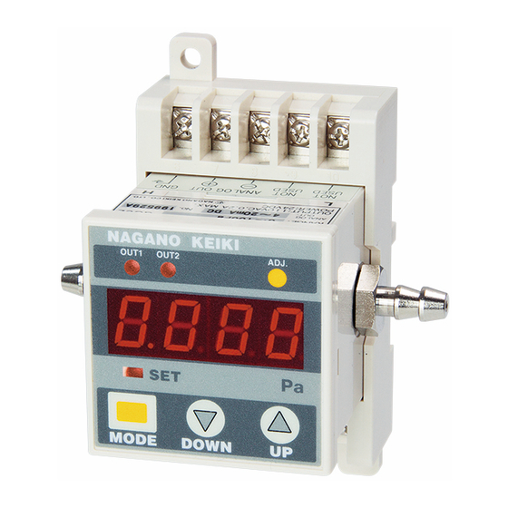
7. Usage and Settings ■ 7.1 How to Switch to Each Mode 7.1.1 Modes and Functions コンパレータ設定 Comparator Setting ループチェックモード 機能設定モード Loop Check Mode Function Setting Mode ・ヒステリシスの設定 ・コンパレータ動作の選択 • Hysteresis setting: • Select the comparator operation 設定点、接断差の設定 ・表示の選択 Set the dead band/ set point •... - Page 14 7.1.2 Names and functions of the panel unit コンパレータ(OUT1, OUT2) Comparator (OUT1, OUT2) Operation indication LED (red) 動作表示LED(赤) ADJ.キー ADJ. key コンパレータ出力のモニタで、 ゼロ点調整時に使用します。 To use during zero point adjustment 出力ON時点灯します。 LED to display 圧力・設定値表示LED Setting Mode (SET) pressure/ set value 設定モード(SET)動作表示LED(橙)...
-
Page 15: Function Setting Mode
■ 7.2 Function Setting Mode 7.2.1 Setting procedure In the Measurement Mode, ”SET LED” flashes when the key is held down for 3 seconds or longer and the mode is changed to Function Setting Mode. This figure shows how to: 測定モード... - Page 16 CAUTION When setting value is manipulated in the Function Setting Mode, all setting values, including comparator, are recalculated and setting value is overwritten. If the recalculated setting value falls outside the display range, the setting value will be the maximum value or the minimum value that can be internally processed.
- Page 17 e.g.) For the pressure range 0 to 10 kPa (0 to 100% F. S.), change the product displayed with 0.00 to 10.00 kPa, to 0 to 1020. 2 → Decimal point position 0 → Display value of the minimum pressure range 1000 →...
-
Page 18: Comparator Setting Mode
■ 7.3 Comparator Setting Mode 7.3.1 Setting The comparator has two points of OUT1 and OUT2 built-in, and two kinds of operations “Hysteresis (maximum and minimum)” and “Window Comparator” can be selected at once. Both can set ON/OFF delay time of up to two seconds independently for OUT1 and OUT2. When the output condition of the comparator described below is satisfied, each output turns on and “Comparator Operation LED (OUT 1, OUT 2)”... - Page 19 CAUTION If the set value of the comparator is outside the display range, it may be rewritten during Function Setting Mode operation. TY-GC62-010A Rev.2...
-
Page 20: Comparator Operation
■ 7.4 Comparator Operation 7.4.1. Hysteresis operation (1) Maximum setting The comparator operates with the set value (A) as the maximum set point. The comparator operates with the value (b) as maximum when (b) is set to a positive numerical value (including 0). Pressure ON Delay (b) Dead band... -
Page 21: Other Functions
■ 7.5 Other Functions 7.5.1 Basics of key operation keys to enter the value to be set in each mode. The value increases with and decreases with key. When keys are held down for 0.5 seconds or longer, it repeats at the speed of 3 steps, and the value increases or decreases. keys to select and set Comparator Operation Mode, unit and filter in Function Setting Mode. - Page 22 7.5.5. Key lock function The key operation can be voided in order to prevent rewriting of the value set by mistake. Once the key is locked, switching to other modes becomes unavailable except for peak hold function. The key can not be unlocked even when the power is turned off and on again, and can be released only by unlocking it.
-
Page 23: Measures Against Noise
8. Measures against Noise ■ 8.1 Effects of Noise If intermittent changes in measurement values or output are found, or if pressure values different from actual ones are indicated, they may be affected by noise. Generally, sources of noise include power supply, an output cable, peripheral equipment, and wiring. Values may be subject to effects of noise depending on the installation place or position of the product. -
Page 24: Maintenance
10. Maintenance ■ 10.1 Periodic Inspection Both the detection part and the circuit part of this product do not have moving parts. Therefore, there could be no adjustment deviation. However, there may be aging depending on usage conditions, we recommend periodic inspection about once every six months. Perform calibration as necessary. - Page 25 ■MEMO TY-GC62-010A Rev.2...
- Page 26 For other questions, contact our sales office nearest you, or call the number below. GC62 Digital Differential Pressure Gauge User Manual April 2019, Rev. 2 Website: http://www.naganokeiki.co.jp/?lng=eng NAGANO KEIKI CO., LTD. Head office 1-30-4, Higashi-magome, Ota-ku, Tokyo 143-8544 Phone: +81-3-3776-5328 Fax: +81-3-3776-5447...
Need help?
Do you have a question about the GC62 Series and is the answer not in the manual?
Questions and answers