Table of Contents
Advertisement
Quick Links
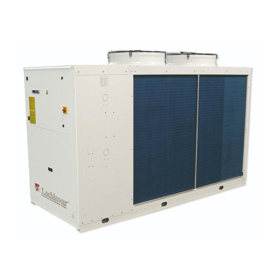
AMICUS HT RANGE
INSTALLATION, COMMISSIONING
AND SERVICE MANUAL
HIGH EFFICIENCY AIR TO WATER HEAT PUMPS
WITH E.V.I. COMPRESSORS
LZT P2U/P2S SERIES
MODELS 252 - 1202
Incorporated in this document are the following:
• Declaration of conformity
• Technical manual
Multiple instructions:
Consult the specific part
MTEC.5001.GB-A-1 Operation and maintenance manual LZT series English Rev. A 11-2020 Lochinvar
Read and understand
the instructions before
undertaking any work on
the unit
Original Instructions
Advertisement
Table of Contents

Related Manuals for Lochinvar AMICUS HT Series


Summary of Contents for Lochinvar AMICUS HT Series
- Page 1 Incorporated in this document are the following: • Declaration of conformity • Technical manual Read and understand Multiple instructions: the instructions before Consult the specific part undertaking any work on the unit MTEC.5001.GB-A-1 Operation and maintenance manual LZT series English Rev. A 11-2020 Lochinvar Original Instructions...
-
Page 2: Table Of Contents
INDEX 1. INTRODUCTION ....................................4 1.1 Preliminary information ..............................4 1.2 Aim and content of the manual ............................4 1.3 How to store this manual ..............................4 1.4 Manual updates ................................4 1.5 How to use this manual ..............................4 1.6 Potential risks .................................. - Page 3 5. UNIT START UP....................................38 5.1 Preliminary Checks ................................ 38 5.2 Position of the control panel ............................40 5.3 How to remote the control panel ............................ 41 6. USE ......................................43 6.1 Switch the unit on ................................43 6.2 Stop ....................................44 6.3 How to change the set points ............................
-
Page 4: Introduction
1. INTRODUCTION 1.1 Preliminary information Reproduction, storage or transmission of any part of this publication in any form, without the prior written consent of the Company, is prohibited. The unit to which these instructions refer, is designed to be used for the the purposes described and to be operated in accordance with these instructions. -
Page 5: Potential Risks
1.6 Potential Risks Whilst the unit has been designed to minimize any risk posed to the safety of people who will interact with it, it has not been technically possible to eliminate completely the causes of risk. It is therefore necessary to refer to the requirements and symbolism below: POTENTIAL LOCATION OF METHOD OF INJURY... -
Page 6: General Description Of Symbols Used
1.7 General Description of Symbols Used Safety symbols combined in accordance with ISO 3864-2: BANNED A black symbol inside a red circle with a red diagonal indicates an action that should not be performed. WARNING A black graphic symbol added to a yellow triangle with black edges indicates danger. ACTION REQUIRED A white symbol inserted in a blue circle indicates an action that must be done to avoid a risk. -
Page 7: Safety Symbols Used
1.8 Safety symbols used GENERAL RISK Observe all signs placed next to the pictogram. The failure to follow directions may create a risk situation that may be injurious to the user. ELECTRICAL HAZARD Observe all signs placed next to the pictogram. The symbol indicates components of the unit and actions described in this manual that could create an electrical hazard. -
Page 8: Unit Identification
1.10 Unit identification Each unit has a rating plate that provides key information regarding the machine. The rating plate may differ from the one shown below as the example is for a standard unit without accessories. For all electrical information not provided on the label, refer to the wiring diagram. A facsimile of the label is shown below: Manufacturer: FO337725 The MXL Centre, 7 Lombard Way... -
Page 9: Safety
2. SAFETY 2.1 Warning re potentially hazardous toxic substances 2.1.1 Identification of the Type of Refrigerant Fluid Used: R410A • Difluoromethane (HFC-32) 50% by weight CAS No.: 000075-10-5 • Pentafluoroethane (HFC-125) 50% by weight CAS No.: 000354-33-6 2.1.2 Identification of the Type of Oil Used. The lubricant used is polyester oil. -
Page 10: Prevention Of Inhalation Of High Vapor Concentrations
2.3 Prevent inhalation of high vapor concentration Atmospheric concentrations of refrigerant must be minimized and kept to a level that is below the occupational exposure limit. Vapor is heavier than air and can form dangerous concentrations near the ground where the ventilation rate is lower. Always ensure adequate venti- lation. -
Page 11: Technical Characteristics
3. TECHNICAL CHARACTERISTICS 3.1 Unit description The LZT series of high efficiency heat pumps has been specifically designed for use with radiant floor heating systems or those applications where it is necessary to have maximum efficiency when heating. They have been optimized on heating mode, are able to produce water up to 65°C and can operate down to -20°C ambient temperature. All versions are supplied with reverse cycle valve used for winter defrost;... -
Page 12: Versions
If required (available as an option), the microprocessor can be configured in order for it to connect to a site BMS system thus enabling remote control and management. The Lochinvar technical department can discuss and evaluate, in conjunction with the customer, solutions using MODBUS protocols. -
Page 13: Accessories Description
water. The controller has dual heating set points (heating and DHW) and can also control a three port diverting valve that directs the DHW to the cylinder. DHW production has priority irrespective of the mode of operation of the unit. The unit is normally used with two pipe water based change-over systems. -
Page 14: What Is The E.v.i. Technology (Enhanced Vapour Injection)
3.4 What is the E.V.I. technology (enhanced vapour injection) EVI stands for “Economised Vapour Injection.” The technology involves injecting refrigerant vapour into the middle of the compression process, a procedure that significantly boosts capacity and efficiency. Each scroll compressor used in these units is similar to a two-stage compressor with built-in inter-stage cooling. -
Page 15: Technical Data
3.5 Technical data Heating only version (HH) LAHP- LAHP- LAHP- LAHP- LAHP- LAHP- LAHP- LAHP- LAHP- Model 252HT 302HT 432HT 492HT 602HT 752HT 852HT 1002HT 1202HT Efficiency data - part L2 Heating capacity (EN14511) 41.2 49.2 57.4 65.6 79.9 87.2 100.7 Total power input (EN14511) 11.8... -
Page 16: Operation Limits
3.6 Operation limits (HA/HE versions) Heating mode Heating mode with head pressure control (DCCF) Ambient temperature (°C) 3.6.1 User heat exchanger water flow rate The nominal water flow rate given is referred to a ∆t of 5 °C. Maximum flow rate allowed is the one that presents a ∆t of 3°C: higher values may cause too high pressure drop. -
Page 17: Domestic Hot Water Production
If the unit is installed in particularly windy areas, it will be necessary to provide some windbreaker barriers to avoid any malfunction. We suggest to install the barriers only if the wind exceeds 2,5m/s. The units, in their standard configuration, are not suitable for installation in saline environments. In WINTER mode, the unit can be started with external air of -20°C and cold inlet water (about 20°C). -
Page 18: Compressor Capacity Steps
3.8 Compressor capacity steps NUMBER of COMPRESSORS Model 1002 1202 3.9 Correction tables 3.9.1 Operation with glycol Glycol percentage Freezing point (°C) IPCF WFCF PDCF -3.2 0.985 1.02 1.08 -7.8 0.98 0.99 1.05 1.12 -14.1 0.97 0.98 1.09 1.22 -22.3 0.965 0.97 1.14... -
Page 19: Sound Data
3.10 Sound data HA / XL Octave bands (Hz) Mod. dB(A) dB(A) 252/HA/XL 85,1 76,3 70,2 68,7 67,6 62,2 58,8 49,7 85,9 312/HA/XL 85,1 76,3 70,2 68,7 67,6 62,2 58,8 49,7 85,9 432/HA/XL 86,1 77,3 71,2 69,7 68,6 63,2 59,8 50,7 86,9 492/HA/XL... -
Page 20: Installation
4. INSTALLATION 4.1 General safety guidelines and and use of symbols Before undertaking any task the operator must be fully trained in the operation of the machines to be used and their controls. They must also have read and be fully conversant with all operating instructions. All maintenance must be performed by TRAINED personnel and be in accordance with all national and local regu- lations. -
Page 21: Inspection
After receiving the unit, immediately check its integrity. The unit left the factory in perfect conditions; any eventual damage must be questioned to the carrier and recorded on the Delivery Note before it is signed. Lochinvar must be informed within 24 hours of delivery of any damage along with pictures so this damage can be assessed. -
Page 22: Lifting And Handling
4.7 Lifting and handling When unloading the unit, it is strongly recommended that sudden movements are avoided in order to protect the refrigerant circuit, copper tubes or any other unit component. Units can be lifted by using a forklift or, alternatively, using belts. Take care that the method of lifting does not damage the side panels or the cover. - Page 23 Amicus HT LAHP252 to LAHP1202 Amicus HT heat pump model Legend Data Unit LAHP- LAHP- LAHP- LAHP- LAHP- LAHP- LAHP- LAHP- LAHP- 252HT 302HT 432HT 492HT 602HT 752HT 852HT 1002HT 1202HT Height 1466 1466 1676 1676 1839 1839 1892 1892 1892 Length 1915...
-
Page 24: Installation Of Rubber Vibration Dampers (Kavg)
4.9 Installation of rubber vibration dampers (KAVG) All units should be installed on vibration dampers in order to prevent the transmission of vibration to the supporting surface and reduce the noise level. Rubber vibration dampers are available as an option in the catalogue. The vibration dampers (optional) are supplied by the factory in separate packaging. -
Page 25: Installation Of Condensate Drip Tray (Brca)
4.11 Installation of condensate drip tray (BRCA) In heating and domestic hot water mode, the unit can produce a quantity of condensate, depending upon the am- bient conditions and the working hours. This condensate may freeze in severe ambient conditions. The unit must therefore be installed in such a way as to prevent a slipping hazard to the user or third parties due to the presence of ice around the heat pump. -
Page 26: Hydraulic Connections
4.12 Hydraulic connections The water pipe-work must be installed in accordance with national and local regulation and can be made from copper, steel, galvanized steel or PVC. The Pipework must be designed to cater for the nominal water flow and the hydraulic pressure drops of the system, a maxi- mum pressure drop of 300 Pa/m run being typical. -
Page 27: Hydraulic Components
4.14 Hydraulic components 4.14.1 P2S Versions P2U Versions User Circuit The water pump must be installed with the supply side toward the water inlet connection of the unit. 4.14.2 P2S Versions + A1NTU P2U Versions + A1NTU User Circuit Rev. A 11-2020... -
Page 28: User Circuit Minimum Water Content
4.15 User circuit minimum water content Heat pump units need a minimum water content inside the user circuit in order to guarantee the correct functioning of the unit. A correct water content reduces the n° of starts-and-stops of the compressors and this extends the operating life of the unit and allows a reduced reduction of the hot water temperature during the defrosting cycle. -
Page 29: Typical Installations
This drawing is for guidance only. ISOLATION VALVE NON RETURN VA Lochinvar Ltd reserves the right to change specifications without prior notice. AIR SEPARATOR DIRT SEPARATOR All necessary additional valves and fittings to be determined by those other than Lochinvar Ltd. -
Page 30: Wiring Connections: Preliminary Safety Information
4.20 Electric connections: preliminary safety information The electric panel is located inside the unit at the top of the technical compartment where the various components of the refrigerant circuit are also to be found. To access the electrical board, remove the front panel of the unit: Power connections must be made in accordance to the wiring diagram enclosed with the unit and in accordance to the norms in force. -
Page 31: Electric Data
4.21 Electric data The electrical data reported below refer to the standard unit without accessories. In all other cases refer to the data reported in the attached electrical wiring diagrams. The line voltage fluctuations can not be more than ±10% of the nominal value, while the voltage unbalance between one phase and another can not exceed 1%, according to EN60204. -
Page 32: Electric Connections
4.22 Electric connections 4.22.1 Power supply and electrical connections Input for electrical connections Input for power supply The numbering of the terminals may change without notice. For their connection is mandatory to refer to the wiring diagram supplied along with the unit. 4.22.2 Remote wiring connections (compulsory) All terminals referred to in the explanations below will be found on the terminal board inside the electrical box. - Page 33 DOMESTIC HOT WATER CIRCUIT PUMP In standard configuration, the microprocessor control of the unit switches off the user water pump when the set point has reached or if the unit is in standby. This strategy provides a sub- stantial reduction of energy use. 4.22.3 Remote wiring connections (optional) 3 WAY ON/OFF VALVE The 3 way valve is used with 2 pipe systems to produce domestic hot water;...
- Page 34 HEATING CABLE This is used to prevent freezing of the condensate produced, in the outlet of the drain tray. The maximum current must not excced 0.5 A relating to a maximum power of 100 W. The heating cable is operated in conjunction with the electric heater in the condensate drain tray. 4.22.4 Factory fitted wiring connections WEATHER COMPENSATED SENSOR (BTE) This is used to measure the ambient temperature enabling weather compensation modulation of...
-
Page 35: Positioning Of The User Circuit Water Inlet Sensor (Bti)
1 x ASHP working with a buffer provding heating SHEET SIZE SCALE DRAWING NO. Lochinvar Ltd reserves the right to change specifications without Rev. A 11-2020 All necessary additional valves and fittings to be determined than Lochinvar Ltd. Lochinvar Limited may provide technical advice and guidance... -
Page 36: Refrigerant Circuit Layout
4.24 Refrigerant circuit layout 4.24.1 Refrigerant circuit layout version P2U - P2S - single finned coil Models 252-752 P2U Version This is a two pipe version that can produce hot water for heating and cold water for cooling. The unit is used with two pipe water based change-over systems. - Page 37 4.24.2 Refrigerant circuit layout version P2U - P2S - two finned coils Models 852-1202 P2U Version This is a two pipe version that can produce hot water for heating and cold water for cooling. The unit is used with two pipe water based change-over systems. It is not able to produce domestic hot water. P2S Version This is a two pipe version that can, in addition to producing hot water for heating and cold water for cooling, also generate domestic hot water.
-
Page 38: Unit Start Up
5. UNIT START UP 5.1 Preliminary checks Before starting the unit the checks detailed in this manual of the electric supply and connections, the hydraulic system and the refrigerant circuit, should be performed. Start-up operations must be performed in accordance with the instructions detailed in the previous paragraphs. If it is required to switch the unit on and off, never do this using the main isolator: this should only be used to discon- nect the unit from the power supply when the unit is to be permanently off. - Page 39 5.1.2 Device Set-point Differential Reset Device Set-point Differential Reset Heating mode °C ----- Domestic hot water mode °C ----- Cooling mode °C ----- Anti-freeze thermostat MANUAL °C Automatic for High pressure switch 3 times (than Low pressure switch manual) Water safety valve (Present in A versions only) Automatic If the unit is required for heating/cooling only (without domestic hot water production) the internal parameter of the micropro- cessor FS1 has to be modified from 2 to 1 in order to avoid configuration alarms.
-
Page 40: Position Of The Control Panel
5.2 Position of the control panel Control panel Unit ON: Heating Unit ON: Heating 00:00 01/01/2014 30.0 °C Evaporator inlet temperature 35.0 °C Evaporator outlet temperature °C External air temp. (FC) San. water temperature 50.0 °C PROBES ALARM SERVICE CIRC. 5.2.1 Display icons Icon Meaning... -
Page 41: How To Remote The Control Panel
5.2.2 Key function Allows to read the value of the probes configured PROBES PROBES PROBES PROBES Allows to switch on the unit in cooling mode PROBES PROBES Allows to read and modify the set point ALARM ALARM ALARM Allows to read and reset the alarms ALARM PROBES SERVICE... - Page 42 5.3.2 Panel mounting connection diagram 5.3.3 Wall mounting connection diagram 5.4.4 Selection built in display or remote keyboard Use the selector switch as shown below to choose the desired display: - Position 0 = display on board - Position 1 = remote display. For remote display electrical connections, always refer to the electrical diagram supplied with the unit.
-
Page 43: Use
6. USE 6.1 Switch the unit on Unit switch-on and switch-off can take place: • From the keyboard • From digital input configured as remote ON/OFF Before first start-up, consult and carry out the operations described in the paragraph “ Periodical checks “. 6.1.1 Switch the unit on from the keyboard PROBES Heating mode... -
Page 44: Stop
6.1.2 Heating and cooling mode The display shows the typical visualization during the unit working in: HEATING MODE COOLING MODE Unit ON: Heating Unit ON: Heating Unit ON: Cooling Unit ON: Cooling 00:00 01/01/2014 00:00 01/01/2014 Evaporator inlet temperature 28.4 °C Evaporator inlet temperature 20.2... -
Page 45: How To Change The Set Points
6.3 Set point To change the set-point from the main screen, press SET. Set point Set point Stand-by Stand-by 00:00 01/01/2014 Energy saving Evaporator inlet temperature 30.0 °C Dynamic set Heating 35.0 °C Evaporator outlet temperature 35.0 °C Sanitary water 50.0 °C External air temp. -
Page 46: Probes Key
6.4 PROBES key To view all the parameters measured by the sensors of the unit press PROBES; Stand-by Stand-by 00:00 01/01/2014 Evaporator inlet temperature 30.0 °C Evaporator outlet temperature 35.0 °C °C External air temp. (FC) San. water temperature 50.0 °C PROBES ALARM... -
Page 47: Circ Key
The alarm status can be: • Reset: the alarm is not active and it is possible to reset it. Press T1 and T2 keys to select the alarm to select it and press RESET key to reset the alarm. • Password: in this case the alarm is no longer active, but you need a password to reset it (please contact the Company). •... - Page 48 Compressor status Unloading status Unloading status Unloading status Compressor status Compressor status Circuit 1 Circuit 1 Circuit 1 Circuit 1 unloading not ongoing 51 % Circuit 2 Circuit 2 Circuit 2 Circuit 2 not configured not configured ALARM EXIT ALARM EXIT Evaporating-condensing probe Evaporator pump status Evaporating-condensing probe Evaporating-condensing probe...
-
Page 49: Service Key
6.7 SERVICE key ENTER EXIT ENTER EXIT Press the SERVICE key to access the following menus: Setting parameters (for service only) Electrical heater and pump down valve status Time and date setting I/O status (Inputs and Outputs) Compressors status Screw compressor information (Not configured) Pumps Auxiliary outputs Circuit maintenance... - Page 50 6.7.1 Service parameters setting To enter service menu select moving between the icons with T1 and T2 keys and press ENTER. The system prompts you to enter the password to access to different levels of security. 1st level password (Pr1) 1st level password (Pr1) ENTER EXIT ALARM...
- Page 51 To modify the value of the parameter: press T1 or T2 to select the parameter to modify then press SET the value start to blinking, press T1 and T2 to modify, than press SET again to confirm. The values available in the group of parameters “Set point” (St) are: summer set point (St01), winter set point (St04), summer regolation band (St07) and winter regolation band (St08).
- Page 52 Weather compensated function This function makes it possible to activate the weather compensation sensor in order to optimize the efficiency of the unit. Automatically it modifies the set-point value with respect to external air temperature: a calculation is performed on the set-point to provide a revised value of set point for higher ambient conditions (see example given below).
- Page 53 The values available in the group of parameters “Sanitary circuit” (FS) are: Sanitary water priority (FS02), Sanitary water set point (FS03), Sanitary water proportional band (FS04) . Parameter group selection Parameter group selection FS02 FS03 45.0 °C FS04 °C Sanitary circuit Sanitary circuit Sanitary water priority Sanitary water priority...
- Page 54 The combinations of time bands that can be set on different days of the week are: 0 = none 1 = Time band 1 2 = Time band 2 3 = Time band 1 and 2 4 = Time band 3 5 = Time band 1 and 3 6 = Time band 2 and 3 7 = All time bands...
- Page 55 6.7.2 Setting date and time moving between the icons with the keys T1 and T2 and press ENTER. To enter this menu select Press T1 and T2 to select the value you want to edit than press SET. The selected parameter will start blinking, press T1 and T2 to set the value and than press SET to confirm.
- Page 56 6.7.3 Compressor maintenance To enter this menu select moving between the icons with the keys T1 and T2 and press ENTER. It is possible to display the compressors working hour and the number of activations. Select the circuit with the keys T1 and T2 than press ENTER to display the parameters.
- Page 57 6.7.6 Alarms To enter this menu select moving between the icons with the keys T1 and T2 and press ENTER. For the management of alarms see par. 6.5. Alarms Alarms b1HP b1HP Attivo Active Aktiv Clock alarm RST ALL RESET EXIT 6.7.7 Alarm log To enter this menu select...
- Page 58 Press T4 and T5 to display all the available parameters. Defrost circ. 1: Defrost circ. 1: cycle not in progress Defrost circ. 1: Defrost circ. 1: cycle not in progress Condenser 1 probe Condenser 1 probe Defrost end set Defrost end set 36.2 bar 36.2 bar Evaporator 1 probe...
- Page 59 6.7.11 Screw compressor (If available) moving between the icons with the keys T1 and T2 and press ENTER. To enter this menu select In the main screen it is possible to display the discharge temperature and the liquid injection set point. Press T1 and T2 keys to select the required circuit than press ENTER key to read the discharge temperature and the status of the valves.
-
Page 60: Acoustic Signal Silencing
6.7.13 Sanitary water moving between the icons with the keys T1 and T2 and press ENTER. To enter this menu select It is possible to read informations of the sanitary water regulation. Press SET key to modify the values. Sanitary water: Sanitary water: Antilegionella cycle: disabled Antilegionella cycle: disabled... -
Page 61: Unit Maintenance
7. MAINTENANCE OF THE UNIT 7.1 General warnings Starting from 01/01/2016 the new European Regulation 517_2014, “Obligations concerning the containment, use, recovery and destruction of fluorinated greenhouse gases used in stationary refrigeration, air conditioning and heat pumps”, became effective. This unit is subject to the following regulatory obligations, which have to be fulfilled by all operators: (a) Keeping the equipment records (b) Correct installation, maintenance and repair of equipment... -
Page 62: Scheduled Maintenance
7.3 Scheduled maintenance The owner must make sure that the unit is periodically inspected, also on-site, adequately maintained, according to the type, size, age and use of the system, and to the indications contained in the Manual. Servicing during the unit’s operating lifetime and, in particular, scheduled leak detection, on-site inspections and check-ups of safety equipment, must be carried out as provided by local laws and regulations in force. - Page 63 7.4.1 Electrical system and adjustment Frequency Action to be performed Every Every Every Every As neces- Monthly sary 2 months 6 months year 5 years Check that the unit works properly and that there are no active warnings Visually inspect the unit Check noise and vibration level of the unit Check operation of safety features and of interblocks Check the unit’s performance...
-
Page 64: Refrigerant Circuit Repair
7.4.3 Compressors Frequency Action to be performed Every Every Every Every As neces- Monthly sary 2 months 6 months year 5 years Visually inspect compressors Check noise and vibration level of the compressors Check the supply voltage of the compressors Check the compressors’... -
Page 65: Decommissioning
8. DECOMMISSIONING 8.1 Disconnect the unit All decommissioning operations must be performed by authorized personnel in accordance with the national legisla- tion in force in the country where the unit is located. • Avoid spills or leaks into the environment. •... -
Page 66: Diagnosis & Troubleshooting
9. DIAGNOSIS AND TROUBLESHOOTING 9.1 Fault finding All units are checked and tested at the factory before shipment, however, during operation an anomaly or failure can occur. BE SURE TO RESET AN ALARM ONLY AFTER YOU HAVE REMOVED THE CAUSE OF THE FAULT; REPEATED RESET MAY RESULT IN IRREVOCABLE DAMAGE TO THE UNIT. - Page 67 Code Alarm Description Cause Solution Alarm ambient sensor Not used Check the electrical connection of Wrong electrical connection, the sensor to the terminal board, if Not used Sensor defect. correct call the service to replace the sensor. AtE1 Evaporator water pump 1 overload AtE2 Evaporator water pump 2 overload In heating mode:...
- Page 68 The company can be contacted for all inquiries regarding the use of its products. The company follows a policy of continuous product development and improvement and reserves the right to modify specifications, equipment and instructions regarding use and maintenance at any time, without notice. Lochinvar Ltd 7 Lombard Way The MXL Centre, Banbury...
Need help?
Do you have a question about the AMICUS HT Series and is the answer not in the manual?
Questions and answers