Table of Contents
Advertisement
Quick Links
SL-PS-I-O Rev B
Solar Pump Station
Installation and Operation
Manual
SPS0250, SPS0500 & SPS1000
This manual must only be used
WARNING:
by a qualified heating installer/
service technician. Read all
instructions, before installing.
Perform steps in the order given.
Failure to comply could result in
severe personal injury, death, or
substantial property damage.
Save this manual for future reference.
Advertisement
Table of Contents

Related Manuals for Lochinvar TISUN PS1000


Summary of Contents for Lochinvar TISUN PS1000
- Page 1 SL-PS-I-O Rev B Solar Pump Station Installation and Operation Manual SPS0250, SPS0500 & SPS1000 This manual must only be used WARNING: by a qualified heating installer/ service technician. Read all instructions, before installing. Perform steps in the order given. Failure to comply could result in severe personal injury, death, or substantial property damage.
-
Page 2: Table Of Contents
HAZARD DEFINITIONS ... 2 1. GENERAL INFORMATION Included components ... 3-4 2. INSTALLING THE SOLAR STATION Installing the solar station on a wall ... 5 Installing the relief valve ... 5 Installation, wall bracket for expansion tank ... 5 Installation, connection lines to tank and collector ... 5 Piping ... -
Page 3: General Information
General Information Before starting work, the Installer must read, understand and note these installation and operating WARNING instructions. The solar pump station may only be installed and maintained by trained professionals. Trainees may WARNING only work on the product under the supervision of an experienced person. All instructions in this Installation &... -
Page 4: General Information Included Components
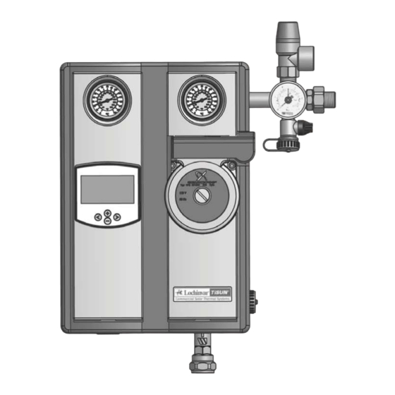
General Information Included Components Solar Station: ■ Grundfos solar circulation pump ■ VFS sensor (flow sensor) ■ 145 psi relief valve, with pressure gauge ■ Multi-function instruments (Flow Check, Thermometer, Fill Valve) ■ EPP two-part bracket with mounting kit Installation kit: ■... -
Page 5: Installing The Solar Station
(field) and safety valve. SL-PS Installation & Operation Manual Installation, wall bracket for expansion tank: (Lochinvar/TiSUN accessories) ■ Fit the wall bracket for the expansion tank (if equipped) to the right of the solar station. ■ Ensure that the corrugated stainless steel hose is long enough for the connection between the pump station and the expansion tank, not forgetting the expansion coupling. -
Page 6: Commissioning Clamp Ring Screw Connections
Technology, installation and commissioning Clamp ring screw connections ■ Cut the copper pipe to length and deburr. ■ First, slide the clamp ring nut over the pipe, then slide the clamp ring. ■ Insert the prepared pipe into the screw connection until its stop is reached. -
Page 7: Commissioning The Solar System General
■ Seal integrity must be tested when commissioning and a pressure test must be completed. ■ Fill the complete solar system with Lochinvar/TiSUN solar liquid only. The mixing ratio should be adapted to local conditions. ■ Never flush or pressure test the complete solar system with just water. -
Page 8: Pressure Loss And Residual Delivery Height
Pressure loss and residual delivery height Solar group with Grundfos UPS 25-58U pump Figure 5-1 (and GF sensor 0.5-3 GPM) residual delivery height SPS0250 Figure 5-2 Solar group with Grundfos UPS 25-99U pump SPS0500 (and GF-Sensor 0.5-10.5 GPM) residual delivery height Figure 5-3 SPS1000 SL-PS Installation &... -
Page 9: Vfs Flow Sensor
VFS flow sensor ■ Vortex flow sensor for liquid media. ■ Measures flow rate and temperature for BTU metering (energy balance, etc.) ■ Zero wear (no moving parts). Figure 6-1 VFS 1-12 flow ouput signal VFS 1-12 output signal flow Assignment of measurement range: 0.26-3.17 gpm is equal to 0.5-3.5V Flow rate calculation: Q = 0.26gpm +[(U-0.5)V/3V]*2.91gpm Figure 6-2 VFS 1-12 temperature output signal... -
Page 10: Technical Data For Solar Station
Technical data for solar station Designation PUMP SOLAR AND TANK CONNECTIONS EXPANSION TANK CONNECTION INSTALLATION OPTIONS HOLDING PLATE FOR WALL MOUNTING MOUNTING MATERIAL FOR WALL MOUNTING CENTER SPACING OF THE PIPING INSULATION FlOW SENSOR AND MEASURING SECTION FILLING AND FLUSHING CONNECTIONS SAFETY GROUP FORWARD FLOW BALL VALVE... -
Page 11: Technical Data For Solar Station
Technical data for solar station Designation GRAVITY BRAKES SOLAR DIAL INDICATOR THERMOMETER FLAT SEALS FOR PUMP FLAT SEAL FOR SAFETY GROUP BLEEDER PIPE SPS0250 / SPS0500 Installation location: forward flow and return ball valves Material: Brass Seal: O-ring 70 EPDM 291 Opening pressure: 2 x 200 mm WS (using metal spring) Can be positioned by moving thermometer handle to 45°F position Max temp 356°F... -
Page 12: Component Breakdown Sps0250
Component breakdown Item – – Solar return ball valve USA Solar forw. flow ball valve USA Solar cross piece cpl. USA Flow sensor housing 0.26-3.17 gpm cpl. w/ fill/ flush valve USA SPS0250- UPS 25/58U - 1 1/2" - 180-F12K03 SPS0500- UPS 25/99U - 1 1/2"... -
Page 13: Sps1000
Component breakdown Item – Solar return ball valve Solar forw. flow ball valve Solar cross piece cpl. USA Sensor direct 0.50- 10.5gpm Figure 9-2 SPS1000 SL-PS Installation & Operation Manual (continued) SPS1000 Name Pumpstation 1000 sq-ft w/ flow sensor and CU Solar bleeder block M36 x 1.5 L=283mm Nut M28 x 1.5mm Clamp ring 22mm... -
Page 14: Service
Service De-energize and lock the solar control WARNING and pump to prevent them from accidentally being switched back on again by mistake before any maintenance or repair work. Service is not permitted until components and solar liquid have cooled. Air separator ■... -
Page 15: Faults, Causes And Rectifications
■ In the event of cavitation caused by insufficient inlet pressure, increase primary system pressure within allowable range. ■ Check speed setting. If the fault cannot be rectified, please contact your nearest Lochinvar/TiSUN customer service representative. SL-PS Installation & Operation Manual... -
Page 16: Revision Notes
Revision Notes: Revision A (ECO C06520) initial release. Revision B (ECO C07610) reflects formatting adjustments. SL-PS-I-O Rev B 3/11...
Need help?
Do you have a question about the TISUN PS1000 and is the answer not in the manual?
Questions and answers