
Related Manuals for LEYBOLD TRIVAC B D 40 BCS


Summary of Contents for LEYBOLD TRIVAC B D 40 BCS
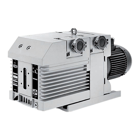
- Page 1 TRIVAC B D 40 BCS / D 65 BCS Rotary Vane Vacuum Pump ■ with mineral oil ■ with PFPE Operating Instructions GA01301_002_C1 Part Nos. 113 88/89/98/98J/99 1129646...
-
Page 2: Table Of Contents
Electrical Connections Operation Media Compatibility Start-up Operation 4.3.1 Pumping of Non-Condensable Gases and Vapours 4.3.2 Pumping of Condensable Gases and Vapours 4.3.3 Operating Temperature Shutdown 4.4.1 Shutdown through Monitoring Components 4.4.2 Controller/Mains Power Failure GA01301_002_C1 - 07/2018 - © Leybold... - Page 3 Replacing the Shaft Seal Removing and Remounting the Pump Module 5.9.1 Removing the Pump Module 5.9.2 Remounting the Pump Module Troubleshooting Wearing Parts and Original Spare Parts Waste Disposal EC-Declaration of Conformity Original installation and operating instructions. GA01301_002_C1 - 07/2018 - © Leybold...
- Page 4 Operating Instructions and follow the information so as to ensure optimum and safe working right from the start. The Leybold TRIVAC BCS has been designed for safe and efficient operation when used properly and in accordance with these Operating Instructions. It is...
-
Page 5: Important Safety Information
Provide an adequate ground connection for the pump so as to avoid any electrostatic charging. GA01301_002_C1 - 07/2018 - © Leybold... -
Page 6: Thermal Hazards
Since not all application related hazards for vacuum systems can be described in detail in these Operating Instructions, Leybold has availa- ble a separate document (Safety Booklet) in which the hazards and general safety concepts for design, operation and maintenance of vacuum systems are explained. -
Page 7: Danger Of Ignition
(LEL) published for the respective gases. Hazard caused by noise CAUTION The noise level produced by the pump less than 60 dB(A). Suitable hearing protection measures must be introduced. GA01301_002_C1 - 07/2018 - © Leybold... -
Page 8: Risk Of Damaging The Pump
Here, the exhaust line must slope down and away from the pump. In the case of custom pumps please note the information provided in the supplementary sheets. GA01301_002_C1 - 07/2018 - © Leybold... -
Page 9: Description
They have been designed particularly for use in connection with corrosive or aggressive media. Moreover, the pump has been prepared for the instal- lation of an electric monitoring facility. Leybold have developed for the TRIVAC BCS a range of accessories which considerably extend the range of applications for this kind of pump. -
Page 10: Function
The gas ballast stops condensation of vapours in the pump chamber up to the limit of the water vapour tolerance as specified in the technical data for the pump. GA01301_002_C1 - 07/2018 - © Leybold... - Page 11 The thermocouple may be accessed through the built-in connector (7/8). Via a second oil fill opening, an exhaust line may be connected for venting the oil case when using the inert gas purging facility. GA01301_002_C1 - 07/2018 - © Leybold...
-
Page 12: Lubricants
If you want to change the type of lubricant Leybold should do the change. In case of operation of a TRIVAC BCS we instruct our vacuum pump oil LVO 100. - Page 13 Work in clean and dry rooms; After having removed the pump from its packaging, start it up immediately. Do not smoke during working with PFPE. As cleaning agents solvents based on hydrofluorether compounds may be used. GA01301_002_C1 - 07/2018 - © Leybold...
-
Page 14: Supplied Equipment
The pump is contained with some silica gel in an air-tight plastic bag. TRIVAC BCS for operatiom with mineral oil Upon delivery from Leybold Cologne the pumps will be filled with LVO 100 oil. TRIVAC BCS for operation with PFPE The pumps will be supplied without lubricant. -
Page 15: Technical Data
Under such operating conditions the motor protection switch may respond. In this case the motor may be started again. In the case of motor 6506961 and 110004011 the minimum permissible temperature is 15 °C at an undervoltage of 380 V -10% = 342 V and a mains frequency of 60 Hz. GA01301_002_C1 - 07/2018 - © Leybold... - Page 16 D 65 BCS-PFPE 40 KF Length l see following page. Fig. 6 Dimensional drawings for the TRIVAC BCS pumps (dimensions a, l, b to b and h are approximate) (dimensions in mm 1inch = 25.4 mm) GA01301_002_C1 - 07/2018 - © Leybold...
- Page 17 1000 m (NHN) Max. ambient temp. w/ operating 40 °C T-board / plug 9 pins Certificates of the motor RoHS RoHS Length of the pump 720 mm (D 40 B) 797 mm (D 65 B) GA01301_002_C1 - 07/2018 - © Leybold...
- Page 18 UL certification mark for energy efficiency for listed products and approved components for Canada and the USA. NOTICE Observe the data given on the motor name plate. For special pumps please note the information contained in the supplemental sheet.. GA01301_002_C1 - 07/2018 - © Leybold...
-
Page 19: Accessories
Limit switch system 40-65 161 07 Electrical indicator system 40-65 160 97 Use only the kind of oil specified by Leybold. As regards the conformity to NOTICE EC directives and standards observe the documentation of the accessory components. 1.5.1 TRIVAC - System... - Page 20 This accessory combines all switch status signals and indicates the status of these switches through LEDs: “GREEN” for normal operation, “RED” for fault. Through a multi-way connector all signals may be accessed for trans mission to a remote processing unit. GA01301_002_C1 - 07/2018 - © Leybold...
-
Page 21: Transport And Storing
When a pump is put into operation after it has been shelved for over one year, standard maintenance should be run on the pump and the oil should also be exchanged (see Section 5.4). We recommend that you contact the Leybold Service. GA01301_002_C1 - 07/2018 - © Leybold... -
Page 22: Installation
The ambient temperature should not exceed +40 °C (104 °F) and not drop below +12 °C (55 °F) (see Section 4.3.3). For installation sites over 1000 m above sea level and/or a relative atmos- pheric humidity of over 90%, you must discuss this with Technical Sales. GA01301_002_C1 - 07/2018 - © Leybold... -
Page 23: Conforming Utilization
Reliably exclude the possibility of an ingress of other oils, greases and rust particles also by the gas being pumped and via the gas ballast. Avoid poten- tial ignition sources, risk of an explosion. GA01301_002_C1 - 07/2018 - © Leybold... -
Page 24: Trivac D65B 3 He For Helium Applications
8 Connector for temperature switch Fig. 7 Connections and controls Use exclusively original spare parts from Leybold in their original packaging. Do not use any second-hand parts. Keep lines, exhaust and other vacuum connections clean and free of oil. If required have the pump and spare parts cleaned by Leybold. -
Page 25: Connection To The System
NOTICE Install the exhaust line with a downward slope (lower than the pump) so as to prevent condensate from flowing back into the pump. If this is not pos- sible, insert a condensate trap. GA01301_002_C1 - 07/2018 - © Leybold... -
Page 26: Electrical Connections
In order to reduce the emission of oil vapours we recommend the installation of an additional exhaust filter (Leybold accessory, see Section 1.5). Depending on the type of application or the kind of pumped media, the corresponding regulations and informati- on sheets must be observed. - Page 27 Spannung To reverse running invert L1 and L2. Drehrichtung ändern: L1 und L2 vertauschen 200-240 V 50/60 Hz 380-400 V 50 Hz 416-480 V 60 Hz Fig. 8.1a Motor connection diagram (motor P/N: 6506961) GA01301_002_C1 - 07/2018 - © Leybold...
- Page 28 Spannung To reverse running invert L1 and L2. Drehrichtung ändern: L1 und L2 vertauschen 200-220 V 50/60 Hz 346 V 50 Hz 380 V 60 Hz Fig. 8.1b Motor connection diagram (motor P/N: 6520731) GA01301_002_C1 - 07/2018 - © Leybold...
-
Page 29: Operation
Avoid exposing any part of the human body to the vacuum. There is the risk of suffering injury. Observe Safety Information 0.1 GA01301_002_C1 - 07/2018 - © Leybold... -
Page 30: Operation
(if possible via a valve). Once all vapours have been pumped off from a process (e.g. during drying), the gas ballast valve can be closed to improve the attainable ultimate pressure. GA01301_002_C1 - 07/2018 - © Leybold... -
Page 31: Operating Temperature
Observe Safety Information 0.3. If – due to the ambient conditions – this temperature range is exceeded at either end of the range, contact Leybold Sales. The motor may accelerate with a delay when simultaneously an undervoltage is present at the motor and the pump is at the minimum permissible and ambient temperature. -
Page 32: Shutdown Through Monitoring Components
In order to prevent the pump from running up unexpectedly after a mains power failure, the pump must be integrated in the control system in such a way that the pump can only be switched on again manually. This applies equally to emergency cut-out arrangements. GA01301_002_C1 - 07/2018 - © Leybold... -
Page 33: Maintenance
Leybold offers practical courses on the maintenance, repair, and testing of TRIVAC BCS pumps. Further details are available from Leybold on request. -
Page 34: Maintenance Plan
= Daily maintenance Exchange of all seals ■ 6m = Six monthly maintenance Functional check ■ a = Annual maintenance n-a = Maintenance every n years This service should be run by the Leybold - Service. GA01301_002_C1 - 07/2018 - © Leybold... -
Page 35: Leybold Service
Maintenance Leybold Service Whenever you send a pump to Leybold, indicate whether the pump is conta- minated or is free of substances which could pose a health hazard. If it is contaminated, specify exactly which substances are involved. You must use the form we have prepared for this purpose;... -
Page 36: Monitoring The Oil Level
Please note the safety information given in Section 0.3 und 0.4. Pumps which have not directly been delivered from Leybold, e.g. in sys tems, may have been filled with oils different from LVO 100. In this case a refill with LVO 100 may cause problems. -
Page 37: Pfpe
When disposing of waste oil, observe the applicable environment protec- tion regulations! When changing the oil use the same type of oil which was previously in the pump. If you want to change the type of oil entirely please consult us first. GA01301_002_C1 - 07/2018 - © Leybold... - Page 38 ■ when pumping contaminated gases ■ when pumping extremely reactive substances. How often a PFPE exchange will be necessary can only be decided on a case-by-case basis depending on the level and type of contamination. GA01301_002_C1 - 07/2018 - © Leybold...
- Page 39 When an exhaust filter with lubricant return has been installed on the pump please also exchange the oil there. We can only guarantee that the pump operates as specified by the NOTICE technical data if the lubricants recommended by us are used. GA01301_002_C1 - 07/2018 - © Leybold...
-
Page 40: Cleaning The Inlet Screen
Lift off the frame (10/2) and remove the internal demister (10/3). Clean all parts and check that they are in perfect condition; if not, replace them with new parts. Reassemble in the reverse order. Torque for the screws (10/6) is 12.5 Nm. GA01301_002_C1 - 07/2018 - © Leybold... - Page 41 Maintenance 1 Screw with small washer, spring, large washer and O-ring 2 Frame for demister 3 Demister 4 Oil case 5 Gasket 6 Fixing screws Fig. 10 Removal and fitting of the internal demister GA01301_002_C1 - 07/2018 - © Leybold...
-
Page 42: Disassembly And Reassembly Of The Electric Motor
Remove the intermediate flange (11/4) together with the electric motor (11/6). Remove the gasket (11/1). Loosen the threaded pin and pull the coupling with the blade wheel (11/2) off the motor shaft. Unscrew the hex. socket screws (11/3. GA01301_002_C1 - 07/2018 - © Leybold... -
Page 43: Replacing The Shaft Seal
Reassemble in the reverse order. Replacing the Shaft Seal This does not apply to the part number 1129646. Please contact the Leybold Service. Required tools: Allen keys size 3, 5 and 8, flat-nose pliers, plastic hammer, shaft seal driver, possibly a puller for the coupling. - Page 44 Pull off the bushing (12/12) from the shaft. We recommend the use of a new shaft seal and bushing for reassembly. Before fitting the new shaft seal, moisten it slightly with a little vacuum pump oil. GA01301_002_C1 - 07/2018 - © Leybold...
- Page 45 Mount the pump-half of the coupling (12/4) on the shaft. Install the spring washer (12/3) and tighten the screw (12/2). Insert the coupling element (12/1) into the coupling and mount the motor (see Chapter 5.7). GA01301_002_C1 - 07/2018 - © Leybold...
-
Page 46: Removing And Remounting The Pump Module
After removing the protective shipping materials, handle the new pump module with care. Before installing a new pump module, remove the four tie rods from the new module and insert them in the old one for protection during shipment. GA01301_002_C1 - 07/2018 - © Leybold... -
Page 47: Remounting The Pump Module
Push the entire pump module (new or repaired) onto the tie rods. Screw on the hex. nuts (14/1) and carefully cross-tighten them NOTICE (torque 17,5 Nm). Mount the oil case together with the gasket (see Chapter 5.6). Fill in oil. GA01301_002_C1 - 07/2018 - © Leybold... -
Page 48: Troubleshooting
1) Bubble test: The warm pump with degassed oil is running without gas ballast and the intake is blanked off. The exhaust line is led into a vessel with water. If an evenly spaced line of bubbles appears then the pump has an external leak. GA01301_002_C1 - 07/2018 - © Leybold... - Page 49 Intake pressure is too high. Lower the intake pressure. Internal demister is clogged. Clean or replace demister. Service Coupling element is worn. Install new coupling element. Vanes or bearings are damaged. Repair pump. Service GA01301_002_C1 - 07/2018 - © Leybold...
-
Page 50: Wearing Parts And Original Spare Parts
Waste oil from vacuum pumps must not be mixed with other substances or materials. Waste oil from vacuum pumps (Leybold oils which are based on mineral oils) which are subject to normal wear and which are contaminated due to the influence of oxygen in the air, high temperatures or mechanical wear must be disposed of through the locally available waste oil disposal system. -
Page 51: Ec-Declaration Of Conformity
EC-Declaration of Conformity GA01301_002_C1 - 07/2018 - © Leybold... - Page 52 Notes GA01301_002_C1 - 07/2018 - © Leybold...
- Page 53 Notes GA01301_002_C1 - 07/2018 - © Leybold...
- Page 54 Many thanks for your understanding. 17200001_002_C0 © Leybold GA01301_002_C1 - 07/2018 - © Leybold...
- Page 55 Person to contact: Calibration: Factory-calibr. Phone : Fax: Quality test certificate DIN 55350-18-4.2.1 End user: A. Description of the Leybold product: Failure description: Material description : Additional parts: Catalog number: Application-Tool: Serial number: Application- Process: Type of oil (ForeVacuum-Pumps) : B.
- Page 56 Sales and Service Germany Great Britain America Leybold Japan Co., Ltd. Tsukuba Technical Service Center 1959, Kami-yokoba Leybold UK LTD. Leybold GmbH Tsukuba-shi, Ibaraki-shi 305-0854 Unit 9 Bonner Strasse 498 Japan Silverglade Business Park D-50968 Cologne Leybold USA Inc. Service:...
Need help?
Do you have a question about the TRIVAC B D 40 BCS and is the answer not in the manual?
Questions and answers