Table of Contents
Advertisement
Quick Links
Advertisement
Table of Contents

Related Manuals for SELVAS Healthcare Accuniq BC380


Summary of Contents for SELVAS Healthcare Accuniq BC380
- Page 2 The device bears the CE label in accordance with the provisions of Medical Device Directive 93/42/EEC. THE PERSONS RESPONSIBLE FOR PLACING DEVICES ON THE EC MARKET UNDER MDD 93/42/EEC SELVAS Healthcare, Inc. 155, Shinseong-ro, Yuseong-gu, Daejeon, 34109 Republic of Korea TEL: 82-42-879-3000, FAX: 82-42-864-4462 VITAKO Sp. z o.o.
-
Page 3: Table Of Contents
CONTENTS INTRODUCTION ··································································································· 5 1. INTENDED USE........................5 2. WORD DEFINITIONS........................ 5 3. CLASSIFICATION AND COMPLIANCE..................6 4. SAFETY PRECAUTIONS......................6 5. SAFETY SYMBOLS AND INFORMATION................11 6. Guidance for Electromagnetic compatibility(EMC) ..............14 ABOUT BODY COMPOSITION ··················································································· 19 TERM AND FUNCTION OF EACH PART ······································································ 21 1. - Page 4 ERROR & REPAIR ································································································· 56 1. Troubleshooting & Repair ··················································································· 56 2. Error Occurrence & Repair ················································································· 57 AFTER SERVICE ··································································································· 58 1. AFTTER SERVICE ·························································································· 58 2. PACKING AND TRANSPORT ············································································ 58 SPECIFICATION ···································································································· 59 WARRANTY ········································································································· 61 INSTRUCTIONS FOR ASSEMBLY ············································································· 62 1.
-
Page 5: Introduction
INTRODUCTION We thank you for choosing the BC380. Please familiarize yourself with these instructions before using this product and always keep them on hand for easy reference. If you are not sure about an operation, or you experience problems while using the product, please contact our service center. We will provide you with detailed instructions. -
Page 6: Classification And Compliance
3. CLASSIFICATION AND COMPLIANCE 1) This device is classified as; - Class 1 type-BF against electric shock - Ordinary equipment without protection against ingress of water - Equipment not suitable for use in presence of a flammable anesthetic mixture by standard of EN 60601-1:2006/A1:2013(Basic safety and essential performance of Medical Electrical Equipment) 2) This device is complied with Class A for Noise-Emission, Level B for Noise-immunity, by... - Page 7 Caution If you have experienced any trouble with the unit, switch it off immediately, and contact our company or its authorized dealer for assistance. If you plan to connect any device from other manufacturers electrically or mechanically Caution to the unit, contact our company or its authorized dealer for instructions before doing When you connect computer or other system to the unit (RS-232C), the attached systems should be those certified by IEC 950 or equivalent standards for data processing equipment.
- Page 8 Caution Cross contamination is possible because this equipment is used with bare hands and feet. Refer to the cleaning and disinfecting methods in this manual. Caution Measurements may be impaired if this device is used near televisions, microwave ovens, X-ray equipment or other devices with strong electrical fields. To prevent such interference, use the meter at a sufficient distance from such devices or turn them off.
- Page 9 This equipment has been tested and found to comply with the limits for medical devices Note according to EN 60601-1-2:2015. These limits are designed to provide reasonable protection against harmful interference in a typical medical installation. This equipment generates uses and can radiate radio frequency energy and, if not installed and used in accordance with the instructions, may cause harmful interference to other devices in the vicinity.
- Page 10 Incorrect operation or failure of user to maintain the unit spares the manufacturer or his Note agent of the responsibility for system’s non-compliance with specifications or responsibility for any damage or injury. This manual is made for informational purposes and this manual and product are not meant to be a substitute for the advice provided by your own physician or other medical expert.
-
Page 11: Safety Symbols And Information
5. SAFETY SYMBOLS AND INFORMATION The International Electro-technical Commission (IEC) has established a set of symbols for medical electrical equipment which classify a connection or warning of any potential hazard. The classifications and symbols are shown below. Save these instructions for your safety. Degree of protection against electric shock: TYPE BF Please observe operating instructions General warning sign... - Page 12 This symbol is used inside system. Identifies the point where the safety ground of the system is fastened to the chassis. Do not open. This is for factory only. Alternating current Direct current Date of manufacture Manufacturer Non-ionizing radiation CE mark Serial No.
- Page 13 Use no hooks For indoor use only RoHS2...
-
Page 14: Guidance For Electromagnetic Compatibility(Emc)
1) Guidance and manufacturer’s declaration – electromagnetic emissions The ACCUNIQ BC380 is intended for use in the electromagnetic environment specified below. The customer or the user of the ACCUNIQ BC380 should assure that it is used in such an environment. Electromagnetic environment – guidance... - Page 15 2) Guidance and manufacturer’s declaration – electromagnetic immunity The ACCUNIQ BC380 is intended for use in the electromagnetic environment specified below. The customer or the user of the ACCUNIQ BC380 should assure that it is used in such an environment. IEC 60601 test...
- Page 16 3) Guidance and manufacturer’s declaration – electromagnetic immunity 2 The ACCUNIQ BC380 is intended for use in the electromagnetic environment specified below. The customer or the user of the ACCUNIQ BC380 should assure that it is used in such an environment. 60601...
- Page 17 To assess the electromagnetic environment due to fixed RF transmitters, an electromagnetic site survey should be considered. If the measured field strength in the location in which the ACCUNIQ BC380 is used exceeds the applicable RF compliance level above, the ACCUNIQ BC380 should be observed to verify normal operation.
- Page 18 4) Recommended separation distances between portable and mobile RF communications equipment and the ACCUNIQ BC380 The ACCUNIQ BC380 is intended for use in an electromagnetic environment in which radiated RF disturbances are controlled. The customer or the user of the ACCUNIQ BC380 can help prevent...
-
Page 19: About Body Composition
ABOUT BODY COMPOSITION 1. Body Composition Human body consists of body fat mass and lean body mass. Lean body mass refers to non-fat components of human body like body water, muscles, minerals, etc. Body water consists of both intra- and extra-cellular water, and the ratio between them is controlled and maintained within a certain range. - Page 20 5. Abdominal Fatness Body fat consists of subcutaneous fat and visceral fat. Visceral obesity is considered to be a critical risk factor along with Percentage of body fat. Lipoprotein lipase can be easily activated in visceral fat, and it causes visceral fat to be dissolved easily.
-
Page 21: Term And Function Of Each Part
TERM AND FUNCTION OF EACH PART 1. Basic Package The package of the ACCUNIQ BC380includes the following components: Name Specification Quantity Main body Accessories User manual CD or Paper Adapter DC 12V, 5A USB Cable Data management program ACCUNIQ Manager (CD) Bolts 6X20mm L-wrench... -
Page 22: Options
2. Accessory Options 1) Ankle electrodes AE-202 Convenience: can measure with one’s socks or stockings on. Ankle electrode ① Selectivity: can choose either plate electrode or ankle electrode. ② Hygienic: protects from mold or bacteria ③ High accuracy: analyzes more accurately for the person whose sole is corneous 2) Professional health counseling support software Health counseling... - Page 23 7) Thermal Paper Thermal Paper Measured result is presented in a simple and easy format. 8) Bluetooth Dongle Bluetooth It allows wireless communication with a PC or mobile device. 9) Wi-Fi Dongle Wi-Fi Dongle 8) Height Meter Height meter This is an instrument to measure subject’s height more accurately and quickly.
-
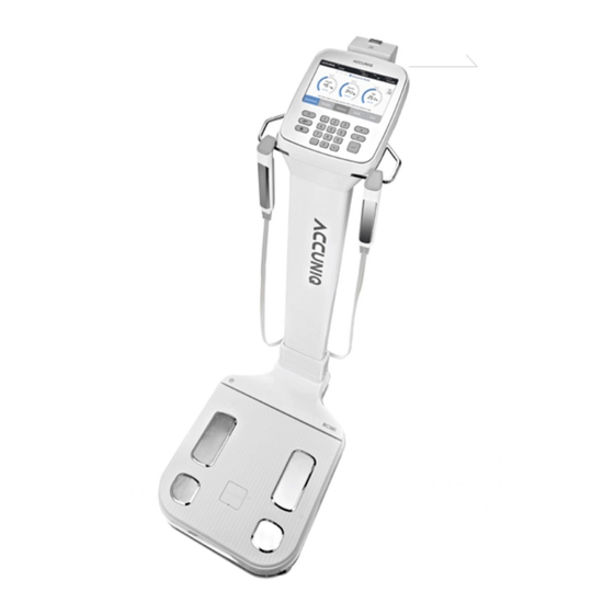
Page 24: Appearance Of The Device
3. Appearance of the device ④ Front Face Color LCD Handle Electrode (Applied Part) ▪ Color LCD panel as touch screen. It displays the procedure and results. ▪ Handle Electrode Handle Electrode measure the impedance by sending harmless electric current to the body. Hold them with the hands during measurement. - Page 25 ▪ Wi-Fi port: Connect the Wi-Fi Dongle. (OPTIONAL) ▪ USB port: Connect a USB drive. (OPTIONAL) ▪ Bluetooth port: Connect via Bluetooth. (OPTIONAL) ▪ Printer port: Connect SELVAS Thermal Printer. (OPTIONAL) ▪ Blood pressure port: Connect SELVAS Healthcare blood pressure monitor (OPTIONAL)
- Page 26 3) Unit Base Plate electrode (Applied Part) Weight scale (Applied Part) ▪ Weight scale: Consists of four plate electrodes and measures weight. ▪ Plate electrode: Measures the impedance. The user should step on it with bare feet.
-
Page 27: Installation
3. This device should be powered only using the cable provided by SELVAS Healthcare. 4. Be careful not to touch the base part of the scale when switching on the device, as any weight on the plate electrode during power on can cause measurement errors with the scale’s zero point. -
Page 28: Peripheral Device Installation
2. Peripheral Device Installation 1) Connecting to a Computer Connect the “PC” port located on the rear panel of this device to the USB port on your computer using the USB cable. Or you can connect through Bluetooth (optional). 1. If using the USB port, the cable should be connected to the computer port on the Note BC380. -
Page 29: Connecting Printer
2) Connecting a Printer ① Connecting the device and the printer directly Connect the A4 printer offered with this device to the “PRINTER” port located on the rear panel of this device via a USB cable. - Page 30 ② Connecting the device, computer, and the printer Connect a computer to the “PC” port located on the rear panel of the device using a USB cable. Connect the printer to the computer with a printer cable. The result sheet can be printed out from the PC program.
-
Page 31: Connecting Blood Pressure Monitor
3) Connecting the Blood Pressure Monitor This device can be connected to the automatic blood pressure monitor from SELVAS Healthcare. (Optional) Connect the blood pressure monitor to the “BLOOD PRESSURE” port located on the rear panel of the device using the blood pressure monitor cable. -
Page 32: Replacing Of Thermal Paper (Option)
4) Replacing of thermal (Optional) You should replace the thermal paper while the power is on. ① Turn the screws counterclockwise and open the cover as shown in the picture. ② Insert the thermal paper in the direction as shown in the picture. ③Insert the edge of the thermal paper into the printer slot just slightly. - Page 33 4-1) FEED/CUT functions of thermal printer • FEED Function On the initial screen, press the " " icon at the left bottom and enter the password ‘5555’ on the key pad. Thermal paper will be printed. • CUT Function On the initial screen, press the " "...
-
Page 34: System Setup
SYSTEM SETUP ‘SYSTEM SETUP’ allows the users to change the setting of operational parameters. Note For the purpose of improvement, the contents in SYSTEM SETUP can be changed. 1. Entering SYSTEM SETUP On the initial screen, press the “ ” icon at the left bottom and enter the password ‘0-0-0-0’. -
Page 35: Menu In System Setup
2. Menu in SYSTEM SETUP Menu items are displayed. The function of each icon is as follows. Menu Setting Item Date / Time Date Type Unit change Basic Setting Language Volume Password Data Check/Print/Delete Data Management Copy data to Excel file Data Backup/Restore Printer connection Select printer type... -
Page 36: Setup
3. Setup (1) Basic settings - Date/Time: Use the ∧, ∨ buttons to set the current date and time. - Date Type: Use the <, > buttons to select the desired date format: YYYY-MM-DD, MM-DD-YYYY or DD-MM-YYYY. - Unit change: Select the units for weight and height in kg / cm or lb / ft. - Language: Set the language of menus and prompts. - Page 37 (2) Data Management - Data Check/Print/Delete: You can view, print or delete data stored on the device. - Copy data to Excel file: Export all or part of saved data to an Excel file. - Data Backup/Restore: export data to a USB drive, or load data from a USB drive into the device. (3) Printer - Printer connection: Connect a printer.
- Page 38 (4) Result Sheet - Result sheet setting: Select whether to print on pre-printed paper or A4 paper. - Logo: Change the logo displayed at the top right of the result sheet. - Adult / Child result sheet setting: Select adult results or child result sheet (optional). - Abdominal analysis result setting: Sets the analysis of abdominal fatness under 18yrs.
- Page 39 (6) Weight/Height - Weight Measurement or Input: You can measure or input your weight. - Weight Calibration: Calibrate the weight value. - Height Calibration: Calibrate the height value. (7) Option Management - Measurement electrode (foot electrode / ankle electrode): You can select which electrode to use. - Optional equipment (Height meter / blood pressure monitor): You can select whether to use these optional devices.
- Page 40 (8) Display - Touch Calibration: Calibrate the touch position of the touch screen. (9) A/S center - Contact Us: check or enter your contact information. - Trouble shooting: See the cause of common problems and how to fix them. - Remote check: The product can be remotely inspected by a SELVAS technician if a problem occurs.
-
Page 41: Measurement And Analysis
MEASUREMENT AND ANALYSIS 1. Precaution for measurement The reliability of the results is only as good as their accuracy. The "Accuracy" of the device is determined by comparing the actual body composition and the results from the Body Composition Analyzer. The "Reproducibility" is determined when the device gives the identical results under the same conditions. -
Page 42: Correct Posture
2. Correct measurement position 1) How to touch electrodes - Make sure that the plate electrodes are clean. - Remove socks or stockings, and then stand on the plate electrodes. - Be sure to remove sweat or foreign matter on the soles of your feet. - Place your bare feet securely on the plate electrodes. - Page 43 2) How to Touch Handle Electrodes - Grip the handle electrodes using your fingers and palms. - The 4 electrodes should be touched equally. - Stretch both arms and spread them 30° from the body. (O) Correct grip (X) Imbalanced touch (X) Grip with only palm Note If 8 electrodes are not perfectly touched during the measurement, the result is not...
-
Page 44: Measurement
3. Measurement 1) Basic analysis (1) Measurement If you want to start measurement, step on the scale of the product. ① Weight measurement - When the subject steps on the scale, the screen changes, and a chime is heard. - Do not move or speak until the measurement is complete. - Page 45 ▪ Input height - Input the subject’s height using the numerical buttons on the key pad. Analysis can not be performed if the user’s height exceeds the input range. ▪ Input age - Input the subject’s age using the numbers buttons on the key pad.
- Page 46 ⑥ Measurement posture 3 - Stretch both arms and spread them 30° from the body. ⑦ Starting measurement When the measurement preparation is complete, the following message is displayed on the screen. “Starting measurement. Don’t move or speak, please.” ⑧ Measuring - During the measurement, the following screen appears.
- Page 47 (2) Result screen ① After analysis is complete, the result is displayed on the screen. ② Scanning QR code - Press the ‘QR code’ on the device screen to enlarge the icon and scan the ‘QR code’ with a mobile device to save the data in the server.
- Page 48 2) Analysis using a height meter SELVAS offers an Ultrasonic Height Meter is an optional accessory. When the height meter is connected to the device, it measures the user’s height more accurately. [Measuring procedure] ① Connect the device to the ultrasonic Height Meter. ②...
- Page 49 3) Analysis Using Blood Pressure Monitor The blood pressure monitor from SELVAS Healthcare, Inc. can be connected to the device as an optional add-on. In this way, the blood pressure can be monitored together with weight control. It helps to manage the body fat while checking the blood pressure simultaneously.
-
Page 50: Result Interpretation
RESULT INTERPRETATION Explanation and criteria of the printed results. 1. Personal Data The subject's ID / name, date, height, weight, age and gender are indicated on the result sheet. 2. Company Logo The measurer can input a customized LOGO such as the name of a hospital, sports center, or obesity clinic, telephone number, address, contact person, etc. - Page 51 * EU and etc. thin normal overweight obese 18.5 ~ ≤ 25 25 ~ ≤ 30 < 18.5 over 30 2) Percent Body Fat (P.B.F., %): It is the ratio (%) of the body fat based on the subject’s weight. low-fat normal over-fat...
- Page 52 1) V.F.A. (Visceral Fat Area): The optimal range is 50 ~ 100 cm (male), 40 ~ 80 cm (female). 2) Visceral Fat Level: The degree of visceral obesity is displayed as a level. ▪ Level 1~ 4 corresponds to subcutaneous fat type ▪...
- Page 53 7. Assessment of E.C.W./T.B.W. Edema is the result of an unbalanced state of intra and extra cellular water. Edema can increase when eating salty food, as a result of malnutrition, postpartum, exercise, temporary fatigue etc. It is measured in 3 levels: Optimal, Borderline, Over. 8.
- Page 54 13. Blood Pressure When the blood pressure monitor supplied from SELVAS Healthcare, Inc. is connected to the unit, blood pressure can be measured and the result can be printed. Systolic blood pressure, diastolic blood pressure, and pulse are printed on the result sheet.
-
Page 55: Storage & Maintenance
10) If foreign substances are introduced, or if the device is exposed to harmful environments, the unit must be examined by a qualified technician before use. 11) Use only the power cable, adapter, and fuses provided by SELVAS Healthcare. Please confirm the covering of the cable, the state of the adapter connection, and other safety checks as below: •... -
Page 56: Error & Repair
ERROR & REPAIR 1. Troubleshooting& Repair Error Cause Repair • Clean the measurement contact areas (the electrodes, your palms and soles) and try When the subject’s body impedance again. Out of range deviates from the limit • Measure again with correct posture. - Insufficient contact with electrodes •... -
Page 57: Error Occurrence & Repair
2. Error & Repair Error code Cause Repair • Try to measure again after cleaning the • Electrode and electrode holders with soft gauze. • Try again after cleaning the hands and soles. measuring parts are not • Check if foreign materials are between 38001 detected or dirty •... -
Page 58: After Service
How to contact our company Write us at: SELVAS Healthcare, Inc. 155, shinseong-ro, Yuseong-gu, Daejeon, 34109 Republic of Korea TEL: 82-42-879-3000 FAX: 82-42-864-4462 (You can also contact the following representative or your local distributor) 2. -
Page 59: Specification
SPECIFICATION Model ACCUNIQ BC380 Measuring method Tetra-polar electrode method using 8 touch electrodes. Frequency Range 5, 50, 250 kHz Measuring site Whole body and Segmental measurement (arms, legs, and trunk) [Result for Body Composition Analysis] Main items Body Composition Analysis (Weight, LBM, Body fat, SLM, Protein,... - Page 60 Atmospheric pressure range 70 kPa (700 mbar) to 106 kPa (1060 mbar) Storage ambient Ambient temperature range -25 to +70 °C Relative humidity range lower than 93 % RH Atmospheric pressure range 70 kPa (700 mbar) to 106 kPa (1060 mbar) Software name and Name: BC380, Version: BC380.K.1.0.00 version...
-
Page 61: Warranty
WARRANTY Warranty Name of product Body Composition Analyzer Name of model ACCUNIQ BC380 Serial number Period of warranty Within 1 year from the date of purchase Date of purchase Customer Add. Name Tel. Dealer (market) Add. Name Tel. Note - When you receive this warranty, make sure that the name of the dealer and the month, day and year of purchase are all completed. -
Page 62: Instructions For Assembly
Assembling Instruction 1. Main Unit Installation For your safety, it is highly recommended that the transporting, unpacking and installation of this product be carried out by two or more people working together. (1) Product installation components 4mm hexagonal wrench Body Cover Main Body M6 plate head bolt X 2... - Page 63 ② Remove the packing band and tape with scissors or a knife very carefully so as to prevent damage to the product. ③ When opening the box and folding the lid, take care not to crush the urethane foam when removing the product protection materials.
- Page 64 (3) Unit Setup ① Two or more workers should remove the product from the box, centering their efforts on the scale. ② Place the main frame of the product on a flat surface with an average slope of less than 10 degrees as shown in the figure.
- Page 65 ③ Make sure that the sides of the vertical column of the frame are aligned at right angles so that they match with the bottom platform. Make sure that the screw holes on the bottom of the vertical column and the main platform are aligned.
- Page 66 ④ One person should hold the body’s frame to prevent it from falling, while the other person removes the packing vinyl from the product. While one person holds the main frame, the other person should use a 4mm hexagonal wrench to insert two M6 bolts into the left and right grooves of the body hinge bracket as shown in the figure.
- Page 67 (4) Assembly of body hinge cover ① Remove the body hinge cover in the direction of the arrow as shown in the figure. ② Attach the body hinge cover to the lower part of the vertical column of the body fat analyzer as shown in the figure, then press on both sides of the body hinge cover to snap it together.
- Page 68 (5) Leveling and power connection Check the level of the installed product. If the product is not level, use the 5 disks on the underside of the platform to adjust the level. Once the product is level, connect the supplied adapter and power cable and turn on the power.
-
Page 69: Assembling The Height Meter (Optional)
2. Installation of Ultrasonic Height Meter (optional) For proper installation, be sure to read and understand the following information before assembling. (1) Height Meter installation components M4 plate head M6 wrench bolt bolt X 2 Height meter body 5mm hexagonal (+) screwdriver Height meter wrench... - Page 70 (2) Preparation before Height Meter installation ① Please turn off the product, and disconnect the adapter jack. After ensuring the floor is clean, lay vinyl or paper on the floor in order to protect the product when laying it down. Make sure that there are no foreign or sharp objects on the floor, as these may cause damage to the product.
- Page 71 (3) Installation of extensometer ① Lay the product on its back as shown. Be careful not to damage the product. Place a support or thick book as shown in the picture so the LCD does not touch the floor. Place the electrode handle in a safe place so that it does not interfere with the assembly of the product.
- Page 72 ③ Connect the cable connector to the connector of the height meter. ④ Turn the height meter base upside down and secure it in the open holes of the scale base plate.
- Page 73 ⑤ Secure the M6 wrench bolts to each hole with a 5 mm hexagonal wrench. ⑥ When the extensometer base is installed, place the product on a level surface. Be careful not to damage the product. Be sure any supports or floor coverings are moved out of the way.
- Page 74 ⑦ The Height meter body consists of 2 parts in total. Take out two extension parts and remove the packing vinyl. ⑧ Place the two extension parts side by side on the floor.
- Page 75 ⑨ When connecting the middle of the upper body to the body base, please position the "D-SUB connector" in the same direction as the figure. Remove the connector cables from both the upper and lower parts, and connect the cables together. ⑩...
- Page 76 ⑪ Fix the two M4 plate head bolts to the left and right holes as shown in the figure using a plus (+) screwdriver. Connection of upper and lower parts of the height meter body is completed. ⑫ Raise the locking lever of the body cover as indicated by the arrow in the figure.
- Page 77 ⑬ As shown in the figure, push the upper part of the rubber pad inside the body cover to move the height meter body easily. Insert the height meter body into the body cover. (The RS-232C connector at the bottom of the height meter body must be connected to the connector connection jack attached to the stand.)
- Page 78 ⑭ Secure the body cover locking lever in the direction of the arrow. ⑮ Slide the height meter head up to level.
- Page 79 ⑯ If the connection of the height meter head is loose, use a flat screwdriver to secure the bolt. Connect the adapter and turn on the power switch.
-
Page 80: Assembling The Ankle Electrode (Optional)
3. Installation of ankle electrode (optional) For your safety, it is highly recommended that the transporting, unpacking and installation of this product be carried out by two or more people working together. (1) Ankle electrode installation components Ankle M6 plate head bolt 4mm hexagonal electrode wrench... - Page 81 ② Lay the product on its back as shown. Be careful not to damage the product. Please use supports or a thick book as shown to prevent the LCD from touching the floor. Place the electrode handle in a safe place so that it does not interfere with the assembly. ③...
- Page 82 ④ Connect the two connectors on the ankle electrode to the connector jacks on the bottom of the scales as shown. ⑤ Align the connector jacks, and push them into the hole in the foot platform, and align it with the M6 bolt locking hole.
- Page 83 ⑥ Hold the ankle electrode with one hand and secure the ankle electrode to the scale with 4 M6 bolts using a 4 mm hexagonal wrench.
- Page 84 ⑦ Attach the ankle electrode to the scales and place the product on a level surface. Be careful not to damage the product. Be sure any supports or floor coverings are moved out of the way. ⑧ Jiggle your ankle electrode to check if it is fixed properly.
- Page 85 ⑨ Power connection After assembling the ankle electrode, connect the supplied power cable and the power supply.
-
Page 86: Assembling The Thermal Printer (Optional)
4. Installation of optional thermal printer For your safety, it is highly recommended that the transporting, unpacking and installation of this product be carried out by two or more people working together. (1) Thermal printer installation components Thermal printer M3 plate head bolt (+) Screwdriver (2) Installation of thermal printer ①... - Page 87 ② Connect the cable connection jack of the thermal printer to the connector on the rear side so that it clicks. ③ Align the thermal printer with the groove on the back of the body fat measurement device and push it horizontally in to place.
- Page 88 ④ Hold the thermal printer with one hand and insert the M3 plate head bolts into the three holes with a plus shape (+) screwdriver. ⑤ Thermal printer installation is completed. (To replace the thermal printer’s paper, please refer to the "Replacing the thermal paper"...
- Page 89 Pass/Fail 4 Measurement Proper measurement Pass/Fail General Judgment Pass/Fail Model ACCUNIQ BC380 Serial No. Installation place Date of purchase Check date Checked by Approved by Copy this sheet for use If repair is required, write down so in the Remarks column.
- Page 90 Pass/Fail Other 1 Clock Present date/time Pass/Fail General Judgment Pass/Fail Model ACCUNIQ BC380 Serial No. Installation place Date of purchase Check date Checked by Approved by Copy this sheet for use If repair is required, write down so in the Remarks column.
Need help?
Do you have a question about the Accuniq BC380 and is the answer not in the manual?
Questions and answers