Table of Contents
Advertisement
Quick Links
Advertisement
Table of Contents

Related Manuals for Martindale Electric ET5


Summary of Contents for Martindale Electric ET5
- Page 1 ELECTRICAL TESTER Instruction Manual...
- Page 2 Where applicable other safety measures such as use of protective gloves, goggles etc. should be employed. If the equipment is used in a manner not specified by Martindale Electric, the protection provided by the equipment may be impaired. Please keep these instructions for future reference. Updated instructions and product information are available at: www.martindale-electric.co.uk...
-
Page 3: Table Of Contents
Thank you for buying one of our products. For safety and full understanding of its benefits please read this manual before use. Technical support is available from 01923 441717 and support@martindale-electric.co.uk. CONTENTS Introduction Inspection Description Accessories Battery Installation Product Specific Safety Information Precautions Operation General... - Page 4 3.17 Resistance Measurement 3.18 Capacitance Measurement 3.19 Frequency & Duty Cycle Measurement 3.20 Temperature Measurement 3.21 Temperature Offset Adjustment 3.22 Continuity Testing 3.23 Diode Testing 3.24 Use as a Non-contact Voltage Detector Maintenance Battery Replacement Test Lead Replacement Calibration Cleaning Repair &...
-
Page 5: Introduction
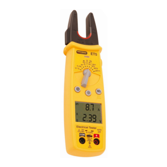
Examine the shipping carton for any sign of damage. Inspect the unit and any accessories for damage. If there is any damage then consult your distributor immediately. 1.2 Description The ET5 is an electrical tester with the following functions: • AC & DC current to 200A •... -
Page 6: Product Specific Safety Information
2. PRODUCT SPECIFIC SAFETY INFORMATION Measurement Category III (CAT III) is applicable to test and measuring equipment connected to the distribution part of the building’s low-voltage MAINS installation. 2.1 Precautions This product has been designed with your safety in mind, but please pay attention to the following warnings and cautions before use. - Page 7 When using test leads, always keep your fingers behind the finger guards on the test lead probes. When this unit is used in combination with test leads, the measurement category of the combination is the lower measurement category of either this unit or the test leads used. Likewise if test lead accessories such as crocodile clips are also used, the measurement category will be the lowest measurement category in that combination.
-
Page 8: Operation
3. OPERATION 3.1 General If the magnitude of a parameter to be measured is uncertain, but known to be within the maximum safe limits of the electrical tester, manually set the range to maximum. E.g. If measuring AC voltage and the voltage magnitude is unknown, set the range to 600V, then if required select the correct range for a satisfactory reading. -
Page 9: Low Battery Indication
3.2 Low Battery Indication The battery capacity is shown by the symbols on the LCD. symbol is flashing followed by a LO.Bt display, the battery If the needs replacing as measurement accuracy can no longer be guaranteed (See section 4.1 Battery Replacement). 3.3 High Voltage / Continuity LED The LED will flash red when the voltage being measured is ≥... -
Page 10: Auto Power Off
Indicates DC measurement Manual ranging is selected Display hold is activated Continuity function is selected Diode testing function is selected Indicates battery level %, °F, Hz Units of measurement being displayed (Upper display) µA, A °C, mV, V, Units of measurement being displayed (Lower display) µF, mF, Ω, kΩ, MΩ, Hz 3.6 Auto Power Off... -
Page 11: Display Hold
To exit manual ranging, hold down the button for 2 seconds. The symbol will no longer be displayed. 3.8 Display Hold To hold a displayed value, press the HOLD button. The LCD will display To exit display hold, press the HOLD button again. 3.9 Backlight/LED Torch To switch on the backlight and LED torch press the button. -
Page 12: Ac Voltage Measurement
CAT III 1000V CAT IV 600V CAT II 1000V ONLY, DO NOT USE on CAT III or CAT IV installations One test lead may be attached to the side of the electrical tester for ease of use when making measurements. 3.12 AC Voltage Measurement Connect the black test lead to the terminal and the red test... -
Page 13: Ac Current Measurement
The AC voltage function defaults to auto ranging and the 5V range. If the 500mV range is required it is manually selected. Taking all necessary safety precautions connect the test leads to the circuit being measured and read the measured voltage from the lower display. -
Page 14: Dc Current Measurement (500Μa Range)
centre of the conductor aligns with and is central to the marks on the fork. Read the measured DC current from the upper display. 3.16 DC Current Measurement (500µA range) Connect the black test lead to the terminal and the red test lead to the terminal. -
Page 15: Frequency & Duty Cycle Measurement
Taking all necessary safety precautions, and observing the correct polarity for electrolytic capacitors, connect the test probes to the capacitor to be measured. If the capacitor being measured is charged, diS.C will be displayed on the LCD. Read the measured capacitance from the lower display. 3.19 Frequency &... -
Page 16: Temperature Offset Adjustment
3.21 Temperature Offset Adjustment The offset adjustment allows an individual Type K thermocouple to be optimised for the best measurement accuracy at a chosen reference temperature. The adjustment is accessed by removing the battery cover (see 4.1). Connect the thermocouple to the input socket and place the thermocouple in a known, stable temperature environment at the reference temperature and allow the readings to stabilize. -
Page 17: Diode Testing
3.23 Diode Testing If the diode to be tested is in circuit be sure the circuit power is switched off. Connect the black test lead to the terminal and the red test lead to the terminal. Set the rotary switch to the position. - Page 18 As the source of a live voltage is approached the buzzer will sound intermittently, the red LED will flash and “-” will be displayed on the upper display. Depending on the voltage level, the closer the proximity of the unit to the voltage source, the more rapidly the buzzer sounds and the red LED illuminates, until both become continuous.
-
Page 19: Maintenance
Martindale Electric recommends that it is returned at least once a year to an approved Calibration Laboratory for recalibration and certification. Martindale Electric is pleased to offer you this service. Please contact our Service Department for details. Email: service@martindale-electric.co.uk Tel: 01923 650660 4.4 Cleaning... -
Page 20: Repair & Service
4.5 Repair & Service There are no user serviceable parts in this unit other than those that may be described in section 4. Return to Martindale Electric if faulty. Our service department will quote promptly to repair any fault that occurs outside the guarantee period. -
Page 21: Warranty
5. WARRANTY AND LIMITATION OF LIABILITY This Martindale product is warranted to be free from defects in material and workmanship under normal use and service. The warranty period is 2 years and begins on the date of receipt by the end user. - Page 22 the validity or enforceability of any other provision or other part of that provision. Nothing in this statement reduces your statutory rights.
-
Page 23: Specifications
Specification ET5 Electrical Tester ELECTRICAL All specified accuracies are at 23°C ± 5°C, <75% RH for 1 year. Temperature Coefficient: < 0.1 x (specified accuracy) per °C. (0°C to 18°C, 28°C to 40°C) DC Voltage Range Resolution Input Accuracy Impedance 500mV 0.1mV... - Page 24 AC Voltage Range Resolution Input Accuracy Impedance 500mV 0.1mV Not specified 0.001V 1 MΩ 0.01V 50-60Hz ± (1.2% of rdg + 5 dgts) 60-500Hz ± (2.0% of rdg + 5 dgts) 500V 0.1V 600V Overload Protection: 600V DC or AC rms DC Current ( function Range...
- Page 25 Capacitance Range Resolution Accuracy ± (3.0% of rdg + 15 dgts) 5μF 0.001μF 50μF 0.01μF ± (3.0% of rdg + 5 dgts) 500μF 0.1μF ± (5.0% of rdg + 20 dgts) 0.001mF Overload Protection: 600V DC or AC rms. Temperature Range Resolution Accuracy...
- Page 26 Minimum pulse width: >1µs. Duty cycle limits: >30% and <70%. Overload protection: 600V DC or AC rms. Duty Cycle Range Frequency Resolution Pulse Accuracy (5V Logic) Range Width 5% to 95% 40Hz to 20kHz 0.1% >10 us ±(2.0% rdg + 10 dgts) Overload protection: 600VDC or AC rms.
- Page 27 Power: 9V, PP3 alkaline battery (IEC 6LR61, NEDA 1604A). Battery life: 50 hours typical with carbon zinc 100 hours typical with alkaline Fork maximum conductor size: 15mm diameter Dimensions: 202.5mm (L) x 51mm (W) x 44mm (D) Weight: Approx. 200g including battery Includes: TL17 test leads, 9V battery, K type thermocouple and instructions ENVIRONMENTAL Location: Indoor use only...
- Page 28 Ver. C1.2 Due to policy of continuous development, Martindale Electric reserves the right to alter equipment specification and description outlined in this document without prior notice. No part of this document shall be deemed to be part of any contract for the equipment unless specifically referred to as an inclusion within such contract.
Need help?
Do you have a question about the ET5 and is the answer not in the manual?
Questions and answers