Table of Contents
Advertisement
Quick Links
Advertisement
Table of Contents

Related Manuals for Martindale Electric VT25


Summary of Contents for Martindale Electric VT25
- Page 1 VT25 / VT28 VOLTAGE TESTER Instruction Manual...
-
Page 2: Table Of Contents
1.3 Safety Advice Introduction 2.1 Inspection 2.2 Description 2.3 Accessories 2.4 Battery Installation Operation 3.1 Description of VT25/VT28 Elements and LED Indicators 3.2 Auto-power On/Off 3.3 Torch 3.4 Low Battery Check 3.5 Removable Probe Tip Covers 3.6 Operating Duty Ratio 3.7 Proving Check... -
Page 3: Safety Information
1. SAFETY INFORMATION REMEMBER: SAFETY IS NO ACCIDENT These instructions contain both information and warnings that are necessary for the safe operation and maintenance of this product. It is recommended that you read the instructions carefully and ensure that the contents are fully understood. Failure to understand and to comply with the warnings and instructions can result in serious injury, damage or even death. -
Page 4: Precautions
1.2 Precautions This product has been designed with your safety in mind, but please pay attention to the following warnings and cautions before use. Warnings In order to avoid the danger of electrical shock, it is important that proper safety measures are taken when working with voltages exceeding 30V AC rms, 42V AC peak or 60V DC. -
Page 5: Safety Advice
1000V AC/DC to earth on a CAT III or CAT II installation and 600V AC/DC to earth on a CAT IV installation. It does not mean it can be used to test for a voltage beyond its maximum specified limits. If the probe tip shrouds are not fitted, great care must be taken when testing CAT III and CAT IV installations to avoid the risk of shorting high energy circuits and arc flash. - Page 6 the parts to be tested, the voltage tester may discharge temporarily the interference voltage to a level below the ELV, but it will be back to the original value when the voltage tester is removed. When the indication “voltage present” does not appear, it is highly recommended installing earthing equipment before work.
-
Page 7: Introduction
If there is any damage then consult your distributor immediately. 2.2 Description The VT25 and VT28 are voltage testers used for proving circuits are dead i.e. not hazardous live. They are constructed in accordance with the latest safety standards. -
Page 8: Operation
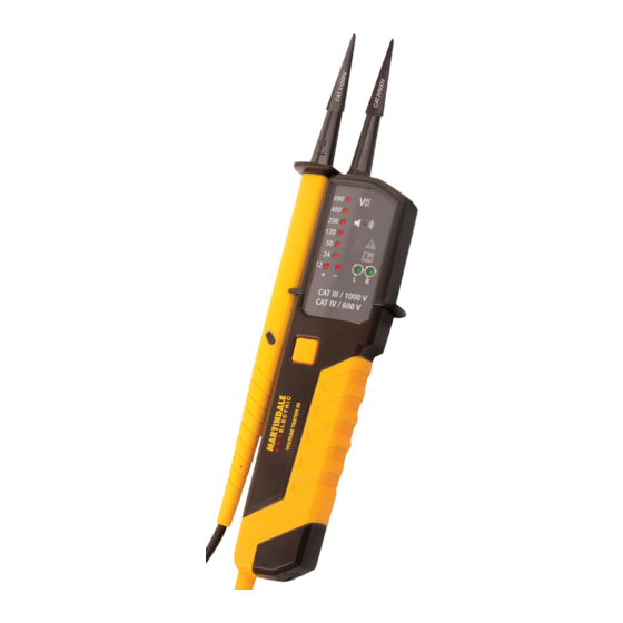
3. OPERATION 3.1 Description of VT25/VT28 Elements and LED Indicators Test probe L1 Test probe L2 Torch Digital Voltmeter LCD (VT28 only) Torch button Main body Battery compartment Buzzer ELV warning and single pole test indicator Continuity indicator Phase rotation indicators Voltage threshold indicators 12V and polarity indicators... - Page 9 Removable probe tip covers Probe tip protective cover Polarity indicators When connected to a DC voltage source either the + or – polarity LED’s will illuminate dependant on polarity. The positive probe is on the main body and is marked with L2 and +. When connected to an AC voltage source both the + and –...
-
Page 10: Auto-Power On/Off
3.4 Low Battery Check Before and after each use short the test probes of the voltage tester together. On the VT25, check for an audible tone and a bright RX LED indication. If there is no audible tone or the RX LED is faint the batteries need to be replaced (see section 4.1 Battery Replacement). -
Page 11: Operating Duty Ratio
The LED’s that illuminate during proving will depend on the magnitude of the proving unit output or the voltage source. See table 1. Also check the buzzer sounds during proving. Table 1. Proving unit type VT25/ Voltage VT28 source PD430 PD690 PD710 LED’s... -
Page 12: Testing For The Presence Of Hazardous Live Voltage
If only the ELV LED illuminates during proving then check the batteries. Warning If the proving device or voltage source exceeds the specified limits of the voltage tester the voltage tester may be damaged and the operator exposed to a shock hazard. -
Page 13: Interference (Phantom) Voltage
3.9 Interference (Phantom) Voltage It is possible for wiring that is ‘dead’ to indicate the apparent presence of voltage at power frequency. If wiring that is live is running in close proximity to the ‘dead’ wiring being tested, there can be capacitive or inductive coupling between the two, thereby causing interference (phantom) voltage. -
Page 14: Digital Voltmeter Lcd (Vt28 Only)
The continuity indicator RX LED will illuminate and the buzzer will sound to indicate circuit continuity. Do not rely solely on the buzzer as an indication of continuity. Always check the voltage threshold LED indications as the buzzer also sounds to indicate the presence of voltage. - Page 15 OPEN Fixed Body Battery Door...
-
Page 16: Calibration
Martindale Electric recommends that it is returned at least once a year to verify physical integrity, electrical specification and insulation integrity. Martindale Electric is pleased to offer you this service. Please contact our Service Department for details. Email: service@martindale-electric.co.uk Tel: 01923 650660 4.3 Cleaning... -
Page 17: Warranty
5. WARRANTY AND LIMITATION OF LIABILITY This Martindale product is warranted to be free from defects in material and workmanship under normal use and service. The warranty period is 2 years and begins on the date of receipt by the end user. This warranty extends only to the original buyer or end-user customer, and does not apply to fuses, disposable batteries, test leads or to... -
Page 18: Specifications
Specification VT25/VT28 Voltage Tester ELECTRICAL Voltage Detector Maximum working voltage: 690V DC & AC rms Nominal voltage threshold indications: 12, 24, 50, 120, 230, 690V AC/DC Nominal voltage threshold tolerance: Conforms to BS EN 61243-3:2014 Internal impedance at ELV a.c.: 260kΩ... - Page 19 Specification VT25/VT28 Voltage Tester GENERAL Power: 2 x 1.5V, AAA alkaline batteries (IEC LR03, NEDA 24A) Battery consumption: 80mA max. Dimensions packed: 285 x 72 x 41 mm Weight packed: approx. 250g Includes: 2 x 1.5V AAA batteries, 2 x probe tip...
- Page 20 • Voltage Indicators • Specialist Metrohm Testers (4 & 5kV) • Specialist Drummond Testers Martindale Electric Co. Ltd. Metrohm House, 12 Imperial Park, Imperial Way, Watford WD24 4PP, UK. T: 01923 441717 F: 01923 446900 www.martindale-electric.co.uk sales@martindale-electric.co.uk Ver. B5.0 © Martindale Electric Company Ltd. 2021...
Need help?
Do you have a question about the VT25 and is the answer not in the manual?
Questions and answers