Table of Contents
Advertisement
Available languages
Available languages
Quick Links
P.O. BOX 11846 TUCSON, AZ 85734
(520) 294-3292
• FAX (520) 741-2837
www.iotaengineering.com
INSTRUCTION MANUAL
IMPORTANT SAFEGUARDS
READ AND FOLLOW ALL SAFETY INSTRUCTIONS
WARNING – Dual Power Supply - Risk of shock hazard even if AC power is OFF.
1.
2.
WARNING – Disconnect TSPL (Test Switch Pilot Light) connector before servicing fixture.
3.
WARNING – DO NOT mount near a gas or electric heater.
4.
CAUTION – Before wiring to power supply, turn off electricity at fuse panel or circuit breaker.
CAUTION – Service by Qualified Personnel only. De-energize before opening.
5.
CAUTION – DO NOT attempt to service the battery. It is not field replaceable.
6.
CAUTION – DO NOT use outdoors, in air handler heated outlets, or in hazardous locations. This product is for
7.
use with indoor and damp rated fixtures where the ambient temperature is 0°C minimum to 55°C maximum.
CAUTION – DO NOT use accessory equipment not recommended by the manufacturer.
8.
CAUTION – DO NOT use this equipment for other than its intended use.
9.
10.
Consult your local building code for approved wiring or installation.
11.
The LED Emergency Driver must be connected to an un-switched AC power source of 120 to 277 Vac.
12.
Product output voltage varies accorting to wattage. Refer to Illustration 1 for output voltage per model.
13.
Equipment should be mounted in a location and at heights where it will not be readily subject to tampering by
unauthorized personnel.
14.
Make sure that the branch circuits are derived from a common phase for both normal lighting LED drivers and
the LED Emergency Driver prior to installation.
15.
When used with a switched fixture, it is important that the power to the LED Emergency Driver be provided by
an un-switched circuit.
16.
LED Emergency Drivers are for factory and field installation. They are not field serviceable.
17.
Allow Battery Packs to charge 24 hrs before initial and full-discharge testing.
18.
Emergency lighting system should be tested per all of the required tests and as often as local codes require or
at least quarterly to ensure all components are operational.
19.
Lighting fixture manufacturers, electricians, and end-users need to ensure product system compatibility before
final installations.
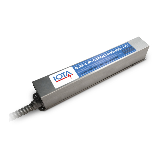
ILB-LP-CP-HE-SD-HV
SAVE THESE INSTRUCTIONS
HIGH EFFICIENCY PERFORMANCE
MEETS CA T20 BATTERY CHARGER
EFFICIENCY STANDARDS
"S" MOUNTING STYLE
HIGH-EFFICIENCY EMERGENCY
LIGHTING EQUIPMENT
FOR LED
Advertisement
Table of Contents

Summary of Contents for IOTA ILB-LP-CP-HE-SD-HV
- Page 1 ILB-LP-CP-HE-SD-HV “S” MOUNTING STYLE HIGH-EFFICIENCY EMERGENCY LIGHTING EQUIPMENT P.O. BOX 11846 TUCSON, AZ 85734 FOR LED (520) 294-3292 • FAX (520) 741-2837 www.iotaengineering.com INSTRUCTION MANUAL IMPORTANT SAFEGUARDS READ AND FOLLOW ALL SAFETY INSTRUCTIONS WARNING – Dual Power Supply - Risk of shock hazard even if AC power is OFF.
-
Page 2: Installation Instructions
STEP 1 - MOUNTING THE ILB-LP-CP-HE-SD-HV ILB-LP-CP-HE-SD-HV FLEX LED DRIVER AND ARRAY COMPARTMENT The ILB-LP-CP-HE-SD-HV should be mounted on or nearby the fixture above the ceiling. The flex conduit should be wired into the driver/lamp compartment or to an electrical junction box TSPL TBTS on the fixture which allows access to the fixture connections. -
Page 3: Completing Installation
OPERATION Normal Mode A.C. power is present. The A.C. Driver operates the LED Module as intended. The ILB-LP-CP-HE-SD-HV is in the standby charging mode. The TSPL will be lit providing a visual indication that the battery is being charged. Emergency Mode ilbcp_tspl_input The A.C. -
Page 4: Testing And Maintenance
TESTING & MAINTENANCE Automatic Testing The ILB-LP-CP-HE-SD-HV is designed to automatically test the emergency function for five minutes each month, and 90 minutes every 12 months. Self-testing works in conjunction with the TSPL assembly. Any detected failures will be indicated by flashing of the bi-color LED. - Page 5 The purpose of this addendum is to sufficiently identify electrical compatibility and predictable emergency light output of the LED luminaire when used with the IOTA ILB-LP-CP Series LED emergency drivers. Verification of these operat- ing traits does not constitute a code-compliant, as-installed emergency egress system. It is still the responsibility of the Designer/Specifier to assure appropriate light levels are achieved during emergency operation of the luminaire in ac- cordance with Federal, state and local municipal codes regarding path of egress illumination.
-
Page 6: Manuel D'instructions
ILB-LP-CP-HE-SD-HV STYLE D’INSTALLATION «S» TROUVEZ VOTRE CHEMIN DISPOSITIF D’ÉCLAIRAGE D’URGENCE À HAUTE PERFORMANCE BOÎTE POSTALE 11846 TUCSON (AZ) 85734 POUR DEL (520) 294-3292 • TÉLÉC. (520) 741-2837 www.iotaengineering.com MANUEL D’INSTRUCTIONS MISES EN GARDE IMPORTANTES LISEZ ET RESPECTEZ TOUTES LES CONSIGNES DE SÉCURITÉ... -
Page 7: Instructions D'installation
CONDUIT ILB-LP-CP-HE-SD-HV FLEXIBLE COMPARTIMENT DU PILOTE DE DEL ET DE L’ILB-LP-CP-HE-SD-HV doit être installé sur le luminaire ou L'ENSEMBLE DE DEL près de celui-ci, au-dessus du plafond. Le conduit flexible doit être raccordé dans le compartiment pilote/lampes ou à LTBT une boîte de jonction électrique sur le luminaire qui permette... -
Page 8: Terminer L'installation
ÉTAPE 4 — CÂBLAGE DE L’ALIMENTATION SECTEUR L’ILB-LP-CP-HE-SD-HV requiert une alimentation secteur sans interrupteur de 120/277 volts. Reliez le fil NOIR à la phase 120/277 et le fil BLANC au neutre. Mettez l’appareil à la terre à l’aide du fil VERT. -
Page 9: Schéma De Câblage
4 CLIGNOTEMENTS ROUGES TEMPÉRATURE HORS PLAGE Test manuel Un test manuel de l’ILB-LP-CP-HE-SD-HV peut être effectué en appuyant et en relâchant le bouton de test LTBT. Entretien Lorsque vous effectuez l’entretien de l’ILB-LP-CP-HE-SD-HV, l’appareil doit être mis complètement hors tension en coupant l’alimentation secteur et en effectuant une des étapes suivantes :... - Page 10 Le présent annexe a pour but d’identifier suffisamment la compatibilité électrique et la puissance d’éclairage de secours prévisible du luminaire à DEL lorsqu’il est utilisé avec les pilotes de secours à DEL de la série IOTA ILB-LP-CP. La vérification de ces carac- téristiques de fonctionnement ne constitue pas un système d’évacuation d’urgence conforme au code, tel qu’installé.


Need help?
Do you have a question about the ILB-LP-CP-HE-SD-HV and is the answer not in the manual?
Questions and answers