Table of Contents
Advertisement
Quick Links
Advertisement
Table of Contents

Related Manuals for Omega SS-015-NA


Summary of Contents for Omega SS-015-NA
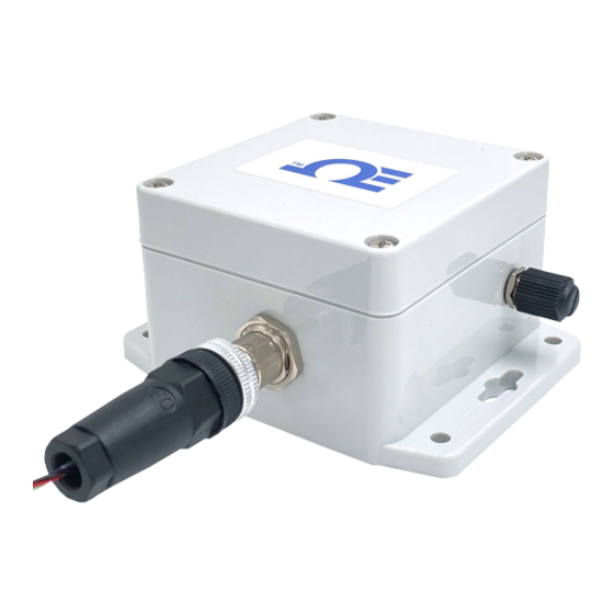
- Page 1 User’ s Gui d e Shop online omega.com M12.5-S-M-FM screw terminal adapter sold separately e-mail: info@omega.com For latest product manuals: www.omegamanual.info SS-015-NA Long Range Wireless Process and Pulse Input Smart Sensor P a g e...
- Page 2 Tel: (203) 359-1660 Fax: (203) 359-7700 e-mail: info@omega.com The information contained in this document is believed to be correct, but OMEGA accepts no liability for any errors it contains and reserves the right to alter specifications without notice. P a g e...
-
Page 3: Table Of Contents
Table of Contents Table of Contents ............................. 3 Notes, Warnings, and Cautions ........................5 Introduction .............................. 6 Specifications ............................7 Hardware Setup ............................8 Digital and Process Input Wiring ........................8 Layer N Cloud Account and Gateway Registration ..................8 SYNC Configuration ........................... 9 Connecting to SYNC –... - Page 4 9.3.4.2 Force Enumeration ................................. 25 9.3.4.3 Radio Type ..................................25 9.3.4.4 Sub GHz Radio Options ..............................25 9.3.4.5 Radio Options (Sub GHz) ..............................25 9.3.4.6 High Power ..................................25 Sensor Interface ............................. 25 9.4.1 Sensor Values ..............................26 9.4.2 Sensor Names ..............................26 Digital Interface .............................
-
Page 5: Notes, Warnings, And Cautions
1 Notes, Warnings, and Cautions If the equipment is used in a manner not specified in this manual, the protection by the equipment may be impaired. Do not operate the equipment in flammable or explosive environments. It is important to read and follow all precautions and instructions in this manual before operating or commissioning this device as it contains important information relating to safety and EMC. -
Page 6: Introduction
• • Quick Start Guide • Layer N Gateway (wireless model only) • 2x C-Cell Batteries • A registered user account with cloud.omega.com Computer with Windows OS • Optional Materials SYNC Configuration software • Downloadable on the Omega website •... -
Page 7: Specifications
Lifetime: Up to 1.5 years with frequency of 1 reading per hour External Power*: 5V @ 1.75 W *External power adapter optional. External power specification based on Omega-specific power adapter. Environmental Operating Conditions for Base Unit: -20°C to 70°C (4°F to 158°F), 90% RH non-condensing... -
Page 8: Hardware Setup
4 Hardware Setup Digital and Process Input Wiring The Layer N SS-015 accepts digital and process inputs through its M12 5-Pin connector. Users connecting wires directly to the SS-015 may refer to the wiring diagram provided below: Process/Analog Digital Mixed Mode Excitation Power Excitation Power Excitation Power... -
Page 9: Sync Configuration
6 SYNC Configuration Layer N Smart devices are easily configurable through Omega’s SYNC configuration software. Ensure SYNC is running on a Windows OS computer before continuing. Connect the SS-015 to a computer running SYNC using a micro-USB 2.0 cable. Note: SYNC is available to download for free on the Omega website. -
Page 10: Input Configuration
• Parity: A means of checking the correctness of a character by adding an extra bit to the character and setting the value based on all the other bits in the character. • StopBits: The number of bits used to indicate the end of the character. When the user has completed setting the communication parameters for the device, click Finish. -
Page 11: Digital Inputs Interface
6.3.2 Digital Inputs Interface In digital inputs mode, the SS-015 accepts digital pulse inputs and may be configured to monitor the on/off state of the input signals, the pulse rate or pulse duty cycle of the primary input, the up/down count of the primary input, or the pulse delay between two signals. -
Page 12: Pulse Measurements
6.3.2.1 Pulse measurements Pulse measurements include Digital Input (DIN), Frequency (RATE), Pulse Width (WIDTH), Duty Cycle (DUTY), Phase Delay Between Pulse Inputs (DELAY), Up Counter/Totalizer (COUNT), and Up/Down Counter/Totalizer (UP/DOWN COUNT). All measurements are derived from signal transitions and an internal 32.768 kHz time reference. - Page 13 The Duty Cycle (DUTY) setting measures the percentage of time a pulse is active (high) over the total period of the signal. The duty cycle measurement allows reading the input from PWM control signals. Duty Cycle = X / Y % Figure 12: Duty cycle example The Phase Delay (DELAY) mode measures the delay time in msec between the rising edges of Pulse A and Pulse B inputs.
- Page 14 The Up/Down Counter/Totalizer (UP/DOWN COUNT) mode counts the number of rising edges until the Reset input is activated. Additionally, the direction of the counter may be controlled using the Direction input (Pin 4) so that it counts up when Active and down when Inactive. Note the Direction input replaces the functionality of the Enable input.
- Page 15 6.3.2.1.1 Input Configuration Diagrams The digital pulse input pins can be independently set to either have an internal 1.5k Pull Up (PU) or Pull Down (PD) and can be set to be either Active High or Active Low by selecting Normally Open (NO) or Normally Closed (NC) in the SYNC input configuration interface.
-
Page 16: Mixed Input Interface
The DIN 0 / Pulse A input pin may also be configured for low-level mV input signals. The four selectable ranges determine the turn-on threshold (TH) and the turn-off threshold (TL) which are used to set the ACTIVE level of the digital input. -
Page 17: Process Inputs (Mixed Mode)
The table below shows the binary-weighted values for the 2-bit Digital Input (DIN) function in mixed mode. Input 1 Input 0 Reading Inactive Inactive Inactive Active Active Inactive Active Active 6.3.3.2 Process Inputs (Mixed Mode) The following process input configuration options are available in mixed input mode: 4-20 mA current loop, 0-1.0 V voltage input, 0-2.0 V voltage input. -
Page 18: Advanced Scaling
6.3.4 Advanced Scaling The Layer N SS-015 allows for advanced scaling options on process and pulse inputs only. The Advanced Scaling checkbox can be selected to expand additional configuration options. A gain and/or offset can be applied to the input reading and the displayed unit can be changed. To apply a gain or offset to the input, expand the Scaling menu and ensure that Apply Scaling is checked. -
Page 19: Setting An Alarm
6.3.5 Setting an Alarm Alarms are set by clicking the icon in SYNC on the desired input signal found in the Input Tab. Figure 20: SYNC alarm configuration interface Configure the Condition that triggers the alarm by selecting an option from the drop down such as Above, Below, Outside the Range, or Within the Range. -
Page 20: Device Settings
Device Settings: The Device Settings tab allows users to configure various features on the SS-015 such as saving and loading configuration presets, performing a factory reset of the device, firmware updates, changing between Low Power and High Power mode, and more. 6.4.1 Radio Control –... -
Page 21: Connecting To Your Layer N Gateway
7 Connecting to your Layer N Gateway The SS-015 easily connects to a Layer N Gateway with a one-button pairing feature. Follow the instructions below: Pairing Button LED Status Indicator Figure 23: SS-015 without top cover Step 1: Push the pairing button once on your SS-015. The LED Status Indicator will blink green repeatedly indicating it is Pairing Mode. -
Page 22: Appendix: Ss-015 Registers
9 Appendix: SS-015 Registers The following Appendix provides the registers and list index for the Layer N SS-015 Smart Sensor. This information is intended to aid users who will be making configurations and adjustments to their Layer N SS-015 Smart Sensor through the Command Line Interface or other custom interfaces. -
Page 23: Vbat
Modbus Parameter Name Parameter Description Addr. Addr. 0x0c00 0xf600 Structure Size 12 == 12 bytes of data, including this field 0x0c02 0xf601 VBat Uint16_t - Battery voltage (mV) 0x0c04 0xf602 Reserved for external power supply voltage, reads as 0. (mV) 0x0c06 0xf603 Status... -
Page 24: Battery Capacity
9.3.3.4 Battery Capacity The Battery Capacity bits provide an approximate indication of the remaining battery power. 9.3.3.5 Enumeration Complete The Enumeration Complete bit is set when the device successfully enumerates. 9.3.3.6 Authentication Error This bit is always cleared (0). 9.3.3.7 Password Error If the Password Fault bit is set the user-provided password does not match. -
Page 25: Force Enumeration
These registers may be accessed using I2C based commands directly to the Smart Probe devices or through a set of Modbus-based registers when using Omega Interface devices. Refer to the Smart Sensor Device Interface manual for further information. -
Page 26: Sensor Values
Enumerated Sensor Descriptor IPSO / Sensor Base Config Digital Process Mixed Mode DIN, RATE, WIDTH, DIN, RATE, WIDTH, 0x0060 0x08a8 DUTY_CYCLE, DELAY Process 0 DUTY_CYCLE, DELAY (0xf030) (0xf454) or COUNT) or COUNT **) 0x0068 0x09a8 Process 1 Process 0 (0xf034) (0xf4d4) 0x0150 0x0aa8... -
Page 27: Digital Interface
Digital Interface The Digital interface manages the three digital inputs: Pulse, Enable/Pulse B, and Reset. These are used to drive user- configurable Rate, Delay, Pulse Width, Duty Cycle, Pulse Delay, and counter functions. 9.5.1 Digital Descriptor Offset Name Value Description DIN, FREQUENCY, WIDTH, DUTY_CYCLE, 0x00 Sensor Type... -
Page 28: Digital Configuration Register
9.5.1.3 Digital Configuration Register Digital Configuration Register Assigned/ Apply Available Lock Sensor Range / Type Channel Scaling (See Below) 9.5.1.3.1 Sensor Range / Type Signals Measurement Units of Range / Type Type Measure DIO2 DIO1 ** DIO0 0x00 0x18 INPUT 2 INPUT 1 INPUT 0 0x01... -
Page 29: Digital Device Byte
9.5.2 Digital Device Byte For digital I/O types, the Device Configuration field determines the signal types for each of the channel bits. CHANNEL 0 SIG 2 (ENABLE) SIG 1 (RESET) SIG 0 (PULSE) 7 6 5 Description Description Description 0 0 0 N.O. -
Page 30: Digital Sensor Trigger Function
9.5.4.2 Digital Sensor Trigger Function The Sensor Trigger function is used to reset the IPSO min/max values as well as control the Calibration process. Digital Sensor Trigger Function Reset Min/Max Calibration Calibration Calibration Capture Capture Calibration Reset Status Mode High Start Setting the Reset Min/Max bit to 1 will reset the Min/Max values recorded by the IPSO process. -
Page 31: Process Input Configuration
9.6.1.2.2 Factory Calibrate Factory calibration is available for the SS-015 process inputs. Clearing this bit will disable the factory calibration values. 9.6.1.2.3 Writeable The writeable bit is cleared, indicating that the sensor values may not be overwritten. 9.6.1.3 Process Input Configuration Process Input Configuration Available Channel... -
Page 32: Process Ipso Definition
9.6.4 Process IPSO Definition The IPSO process definition provides signal range, measured min/max values, IPSO object type information. Offset Name Value Description 3317 Current (mA) 0x08a8 Sensor Type 3316 Voltage (mv) 0-24mA 1 – display as xx.x 0x08aa Precision 0-1000 mV -1 –... - Page 33 Department will issue an Authorized Return (AR) number immediately upon phone or written request. Upon examination by OMEGA, if the unit is found to be defective, it will be repaired or replaced at no charge. OMEGA’s WARRANTY does not apply to defects resulting from any action of the purchaser, including but not limited to mishandling, improper interfacing, operation outside of design limits, improper repair, or unauthorized modification.
- Page 34 Where Do I Find Everything I Need for Process Measurement and Control? OMEGA…Of Course! Shop online at omega.com TEMPERATURE M U Thermocouple, RTD & Thermistor Probes, Connectors, Panels & Assemblies M U Wire: Thermocouple, RTD & Thermistor M U Calibrators & Ice Point References M U Recorders, Controllers &...
Need help?
Do you have a question about the SS-015-NA and is the answer not in the manual?
Questions and answers