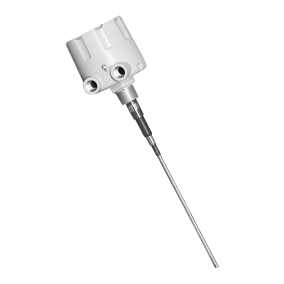
Summary of Contents for Omega LV800 SERIES
- Page 1 User’ s Guide Shop online at omega.com e-mail: info@omega.com For latest product manuals: omegamanual.info LV800 SERIES Capacitance Point Level Sensors...
- Page 2 Approach Directives. OMEGA will add the CE mark to every appropriate device upon certification. The information contained in this document is believed to be correct, but OMEGA accepts no liability for any errors it contains, and reserves the right to alter specifications without notice.
- Page 3 LV 8 0 0 S E R I E S This manual contains the information necessary to ensure a safe and successful installation. Please read and comply with the section on page 9 of this manual pertaining to SAFETY. Doing so will ensure proper oper- ation of the equipment and the safety of all personnel.
- Page 4 The LV800 must be positioned at a point where incoming material will reach and cover the probe in its normal flow, and when receding, will flow away from the probe in an even manner.
- Page 5 E L E C T R I C A L I N S TA L L AT I O N Factory Wiring: The LV800 probe wires are connected to the backside of the PCB. DO NOT alter this connection. Doing will likely cause improper operation of the sensor.
- Page 6 Output Relay Contacts: (See Figure 5) The LV800 is equipped with one or two sets of isolated contacts which indicates whether or not material is being detected with- in the vessel. This output is also influenced by the selection of the "fail-safe"...
- Page 7 LV800 2) Red LED - Its status describes the "operate/output" condi- tion of the LV800. Illumination indicated the relay is in the "operate/material sensed" condition. Its state is influenced by the time delay setting but not by the fail-safe setting. This LED is aimed at the lens in the cover so it can be seen with the cover on or off.
- Page 8 M A I N T E N A N C E Fuse Replacement: The fuse incorporated into the LV800 PCB is not intended for operator replacement. A qualified technician can replace the applicable fuse according to the following specifications. If nec- essary, consult the factory for additional technical assistance or for return of the LV800.
- Page 9 M E C H A N I C A L S DIMENSIONS ARE SHOWN IN INCHES WITH MILLIMETER EQUIVALENT IN BRACKETS Standard Probe Stub Probe...
- Page 10 II and pollution degree 2. Electromagnetic Compatibility (EMC) The LV800 was tested and found to comply with the standards listed below. The LV800 should not be used in residential or commercial envi- ronments. Compliance to EMC standards was demonstrated by means of a test setup using the following installation methods.
- Page 11 Department will issue an Authorized Return (AR) number immediately upon phone or written request. Upon examination by OMEGA, if the unit is found to be defective, it will be repaired or replaced at no charge. OMEGA’s WARRANTY does not apply to defects resulting from any action of the purchaser, includ- ing but not limited to mishandling, improper interfacing, operation outside of design limits, improper repair, or unauthorized modification.
- Page 12 Where Do I Find Everything I Need for Process Measurement and Control? OMEGA…Of Course! Shop online at omega.com TEMPERATURE Thermocouple, RTD & Thermistor Probes, Connectors, Panels & Assemblies Wire: Thermocouple, RTD & Thermistor Calibrators & Ice Point References Recorders, Controllers & Process Monitors...


Need help?
Do you have a question about the LV800 SERIES and is the answer not in the manual?
Questions and answers