Table of Contents
Advertisement
Quick Links
CHART
http://192.168.1.200
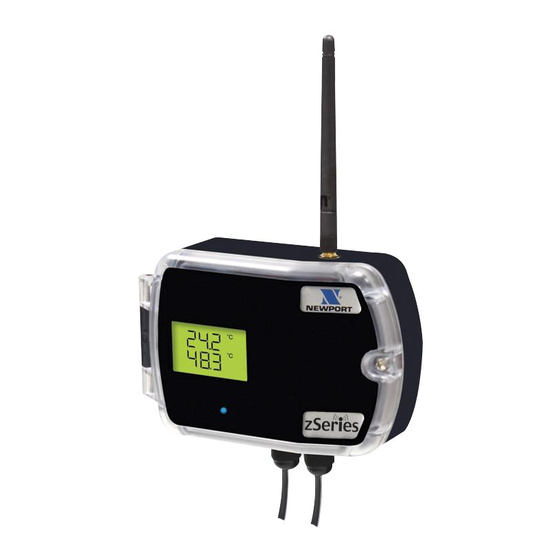
zSeries
Group A
Save Current Graph
35
C
/25
LAB 50 Temp
LAB 50 RH
50
P0 Primary
P1 LAB 50
P2 LAB 100
P3 CLN RM1
5
C/Div
P4 CLN RM2
P5 Primary
P6 OVEN5
P7 Primary
0
Tue Jun 5 18:05:27 PDT 2009
1 Minute
(5 Seconds/Div)
1 Minute
1 Day
1 Week
1 Month
Main Menu
1 Year
1009
hPa
LAB 50 Pres
1200
100%
S0 Secondary
S1 LAB 50
S2 LAB 100
S3 CLN RM1
90
10
hPa/Div
%/Div
S4 CLN RM2
S5 Secondary
S6 OVEN5
S7 Secondary
300
0%
Tue Jun 5 18:11:55 PDT 2009
zED-LCD-AA, zED-DC-H2,
zED-CCELL, zED-H, zCDR
zED-LCD-AA, zED-DC-H2,
zED-CCELL, zED-H, zCDR
User' s Guide
Shop on line at
e-mail: info@omega.com
For Latest Product Manuals
• RoHS 2 Compliant
zSeries Wireless
zSeries Wireless
Sensor System
Sensor System
zED, zED-P, zED-LCD,
zED, zED-P, zED-LCD,
User's Gui d e
Shop online at
®
omega.com
®
omega.com
e-mail: info@omega.com
For latest product manuals:
www.omegamanual.info
omegamanual.info
SM
Advertisement
Table of Contents


Need help?
Do you have a question about the zED and is the answer not in the manual?
Questions and answers